7GR-FKS LUBRICATION OIL PUMP INSTALLATION
PROCEDURE

 11301C
1.INSTALL FRONT CRANKSHAFT OIL SEAL
11301C
1.INSTALL FRONT CRANKSHAFT OIL SEAL
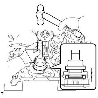
Using SST and a hammer, tap in a new front crankshaft oil seal until its surface is flush with the timing chain cover edge.
- SST
- 09223-22010
09506-35010
- NOTICE:
- ·
Keep the lip free from foreign matter.
·Do not tap on the front crankshaft oil seal at an angle.
·Make sure that the front crankshaft oil seal edge does not protrude from the timing chain cover assembly.
11310
2.INSTALL TIMING CHAIN COVER ASSEMBLY
Remove any remaining seal packing material and be careful not to drop any oil on the contact surfaces of the timing chain cover assembly, cylinder head sub-assembly and cylinder block sub-assembly.
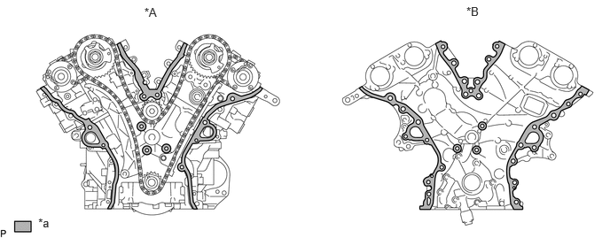
| *A | Cylinder Head and Cylinder Block Side | *B | Timing Chain Cover Side |
| *a | Clean and Degrease | - | - |
- NOTICE:
-
Be sure to clean and degrease the contact surfaces, especially the surfaces indicated in the illustration.
Apply a light coat of engine oil to a new oil pump gasket.
Install the oil pump gasket.
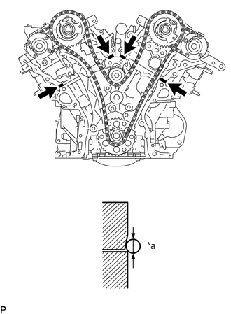
| *a | Seal Diameter |

|
Seal Packing |
Apply seal packing as shown in the illustration.
- Seal packing:
Toyota Genuine Seal Packing Black, Three Bond 1207B or equivalent
- Standard seal diameter:
3.0 to 4.0 mm (0.118 to 0.157 in.)
Apply seal packing to the timing chain cover assembly in a continuous line as shown in the following illustration.
- Seal packing:
Toyota Genuine Seal Packing Black, Three Bond 1207B or equivalent
Toyota Genuine Seal Packing 1282B, Three Bond 1282B or equivalent
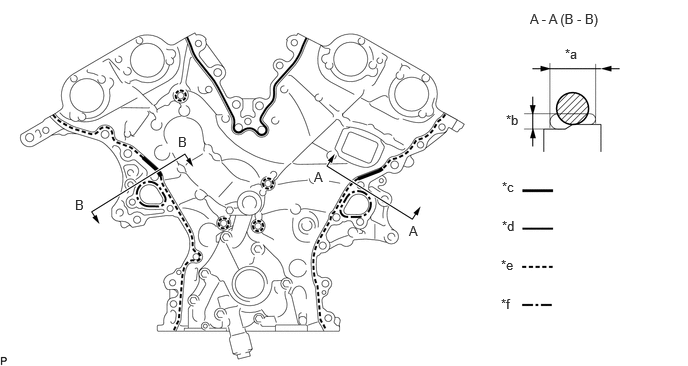
| *a | 9 mm (0.354 in.) | *b | 3 mm (0.118 in.) |
| *c | A - A (B - B):
Continuous line area (Seal packing: Toyota Genuine Seal Packing Black, Three Bond 1207B or equivalent) |
*d | Continuous line area (Seal packing: Toyota Genuine Seal Packing Black, Three Bond 1207B or equivalent) |
| *e | Dashed line area (Seal packing: Toyota Genuine Seal Packing Black, Three Bond 1207B or equivalent) | *f | Alternate long and short dashed line area (Seal packing: Toyota Genuine Seal Packing 1282B, Three Bond 1282B or equivalent) |
- NOTICE:
- ·
When the contact surfaces are wet, wipe them with an oil-free cloth before applying seal packing.
·Install the timing chain cover assembly within 3 minutes and tighten the bolts within 10 minutes after applying seal packing.
- Application Specification:
Area Seal Packing Diameter Application Position from Inside Seal Line Continuous Line Area (A - A (B - B)) 6.0 mm (0.236 in.) or more 5.0 mm (0.197 in.) Continuous Line Area 4.5 mm (0.177 in.) or more 3.0 to 4.0 mm (0.118 to 0.157 in.) Dashed Line Area 3.5 mm (0.138 in.) or more 3.0 to 4.0 mm (0.118 to 0.157 in.) Alternate Long and Short Dashed Line Area 3.5 mm (0.138 in.) or more 2.0 to 3.0 mm (0.0787 to 0.118 in.)
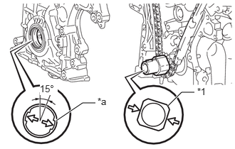
| *1 | Crankshaft |
| *a | Oil Pump Drive Rotor Spline |
Align the oil pump drive rotor spline and crankshaft as shown in the illustration. Install the oil pump drive rotor and timing chain cover assembly to the crankshaft.
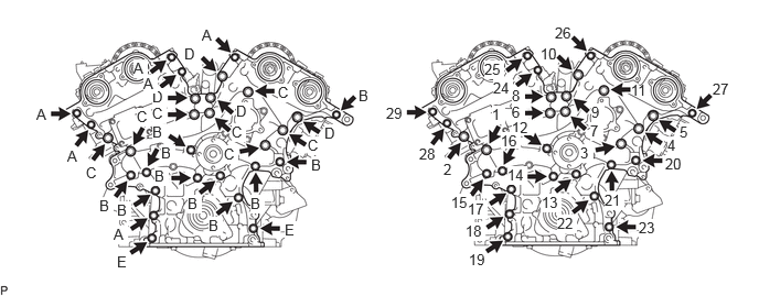
Install the timing chain cover assembly with the 29 bolts, labeled A, B, C, D and E. Tighten the bolts in the order shown in the illustration.
- Torque:
- for bolt A, B and E : 21 N*m (214 kgf*cm, 15 ft.*lbf)
- for bolt C and D : 43 N*m (438 kgf*cm, 32 ft.*lbf)
- Standard Bolt:
Item Length Bolt A 28 mm (1.10 in.) Bolt B 55 mm (2.17 in.) Bolt C 60 mm (2.36 in.) Bolt D 40 mm (1.57 in.) Bolt E 45 mm (1.77 in.)
- NOTICE:
- ·
Make sure that there is no oil on the bolt threads.
·Do not start the engine for at least 2 hours after installation.
·Wipe off any seal packing that seeped out around the surfaces of the oil pan sub-assembly and cylinder head cover sub-assembly and make sure that there is no seal packing seeping out around the edges.
13471
3.INSTALL CRANKSHAFT PULLEY
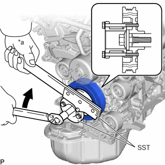
| *a | Hold |
|
|
Turn |
Using SST, install the crankshaft pulley with the crankshaft pulley set bolt.
- SST
- 09213-54015 (91651-60855)
09330-00021
- Torque:
- 260 N*m (2651 kgf*cm, 192 ft.*lbf)
15370B
4.INSTALL CAMSHAFT TIMING OIL CONTROL SOLENOID ASSEMBLY (for Intake Side of Bank 1)
15370B
5.INSTALL CAMSHAFT TIMING OIL CONTROL SOLENOID ASSEMBLY (for Exhaust Side of Bank 1)
15370C
6.INSTALL CAMSHAFT TIMING OIL CONTROL SOLENOID ASSEMBLY (for Intake Side of Bank 2)
15370C
7.INSTALL CAMSHAFT TIMING OIL CONTROL SOLENOID ASSEMBLY (for Exhaust Side of Bank 2)
12101
8.INSTALL OIL PAN SUB-ASSEMBLY
Remove any remaining seal packing material and be careful not to drop any oil on the contact surfaces of the cylinder block sub-assembly, rear oil seal retainer and oil pan sub-assembly.
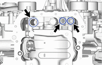
Install 3 new O-rings to the timing chain cover assembly.
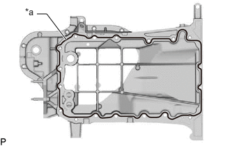
| *a | Seal Packing |
Apply seal packing in a continuous line as shown in the illustration.
- Seal packing:
Toyota Genuine Seal Packing Black, Three Bond 1207B or equivalent
- Standard seal diameter:
3.0 to 4.0 mm (0.118 to 0.157 in.)
- NOTICE:
- ·
Remove any oil from the contact surface.
·Install the oil pan sub-assembly within 3 minutes after applying seal packing.
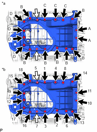
| *a | Types of Nut and Bolt |
| *b | Tightening Order |
|
|
Bolt |

|
Nut |
Install the oil pan sub-assembly with the 16 bolts and 2 nuts.
- Torque:
- for bolt A : 10 N*m (102 kgf*cm, 7 ft.*lbf)
- for bolt B, C, D and nut : 21 N*m (214 kgf*cm, 15 ft.*lbf)
- Standard Bolt:
Item Length Bolt A 16 mm (0.630 in.) Bolt B 45 mm (1.77 in.) Bolt C 25 mm (0.984 in.) Bolt D 70 mm (2.76 in.)
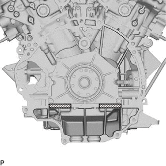

|
Wipe off the Seal Packing |
After tightening the oil pan bolts and nuts wipe off the seal packing material that has seeped out from between the contact surfaces of the cylinder block sub-assembly and oil pan sub-assembly.
15367
9.INSTALL OIL LEVEL SENSOR BRACKET
89491
10.INSTALL ENGINE OIL LEVEL SENSOR
15104
11.INSTALL OIL STRAINER SUB-ASSEMBLY
Apply a light coat of engine oil to a new O-ring.
Install the new O-ring to the oil strainer sub-assembly.
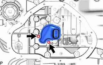
Install the oil strainer sub-assembly with the 2 nuts.
- Torque:
- 10 N*m (102 kgf*cm, 7 ft.*lbf)
12102A
12.INSTALL NO. 2 OIL PAN SUB-ASSEMBLY
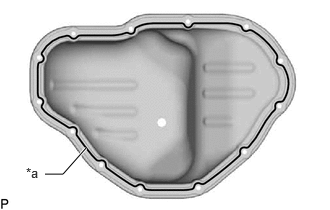
| *a | Seal Packing |
Apply seal packing in a continuous line as shown in the illustration.
- Seal packing:
Toyota Genuine Seal Packing Black, Three Bond 1207B or equivalent
- Standard seal diameter:
2.5 to 3.5 mm (0.0984 to 0.138 in.)
- NOTICE:
- ·
Remove any oil from the contact surface.
·Install the No. 2 oil pan sub-assembly within 3 minutes after applying seal packing.
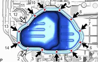
|
|
Bolt |
|
|
Nut |
Install the No. 2 oil pan sub-assembly with the 11 bolts and 2 nuts. Tighten the bolts and nuts uniformly in several steps.
- Torque:
- 10 N*m (102 kgf*cm, 7 ft.*lbf)
- NOTICE:
- ·
Tighten the nuts first. After tightening the bolts, check that the nuts and bolts are tightened to the specified torque.
·Do not start the engine for at least 2 hours after the installation.
11193
13.INSTALL SPARK PLUG TUBE GASKET
11201
14.INSTALL CYLINDER HEAD COVER SUB-ASSEMBLY
Remove any remaining seal packing material and be careful not to drop any oil on the contact surfaces of the cylinder head sub-assembly, timing chain cover assembly and cylinder head cover sub-assembly.
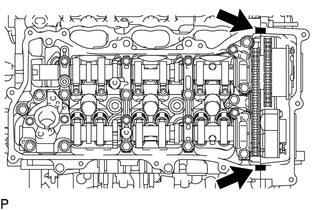
|
|
Seal Packing |
Apply seal packing as shown in the illustration.
- Seal packing:
Toyota Genuine Seal Packing Black, Three Bond 1207B or equivalent
- Standard seal diameter:
2.0 to 3.0 mm (0.0787 to 0.118 in.)
- NOTICE:
- ·
Remove any oil from the contact surface.
·Install the cylinder head cover sub-assembly within 3 minutes and tighten the bolts within 15 minutes after applying seal packing.
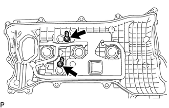
w/o Secondary Air Injection System:
Install 2 new cylinder head cover gaskets.
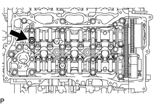
Install a new camshaft bearing cap oil hole gasket RH.
Install a new gasket to the cylinder head cover sub-assembly.
Install a new seal washer to each bolt.
Temporarily install the VVT sensor (for Exhaust Side of Bank 1) to the cylinder head cover sub-assembly.
Temporarily install the VVT sensor (for Intake Side of Bank 1) to the cylinder head cover sub-assembly.
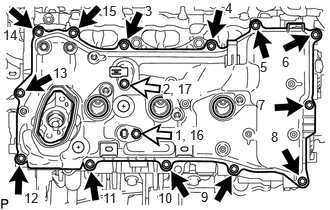
|
|
Bolt A |
|
|
Bolt B |
w/o Secondary Air Injection System:
Temporarily install the cylinder head cover sub-assembly with the 15 bolts. Tighten the bolts uniformly in several steps.
- Torque:
- 10 N*m (102 kgf*cm, 17 ft.*lbf)
- Standard Bolt:
Item Length A 25 mm (0.984 in.) B 23.5 mm (0.925 in.)
- NOTICE:
-
Do not start the engine for at least 2 hours after installation.
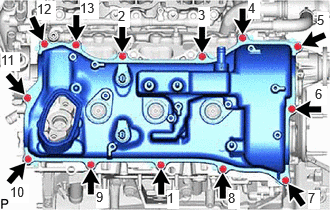
w/ Secondary Air Injection System:
Temporarily install the cylinder head cover sub-assembly with the 13 bolts. Tighten the bolts uniformly in several steps.
- Torque:
- 10 N*m (102 kgf*cm, 17 ft.*lbf)
- NOTICE:
-
Do not start the engine for at least 2 hours after installation.
Install the 2 VVT sensors to the cylinder head cover sub-assembly.
11202
15.INSTALL CYLINDER HEAD COVER SUB-ASSEMBLY LH
Remove any remaining seal packing material and be careful not to drop any oil on the contact surfaces of the cylinder head LH, timing chain cover assembly and cylinder head cover sub-assembly LH.
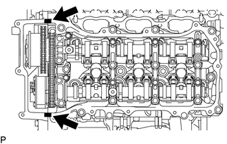
|
|
Seal Packing |
Apply seal packing as shown in the illustration.
- Seal packing:
Toyota Genuine Seal Packing Black, Three Bond 1207B or equivalent
- Standard seal diameter:
2.0 to 3.0 mm (0.0787 to 0.118 in.)
- NOTICE:
- ·
Remove any oil from the contact surface.
·Install the cylinder head cover sub-assembly LH within 3 minutes and tighten the bolts within 15 minutes after applying seal packing.
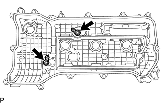
w/o Secondary Air Injection System:
Install 2 new cylinder head cover gaskets.
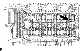
Install a new camshaft bearing cap oil hole gasket LH.
Install a new gasket to the cylinder head cover sub-assembly LH.
Install a new seal washer to each bolt.
Temporarily install the VVT sensor (for Exhaust Side of Bank 2) to the cylinder head cover sub-assembly LH.
Temporarily install the VVT sensor (for Intake Side of Bank 2) to the cylinder head cover sub-assembly LH.
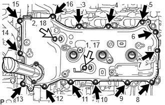
|
|
Bolt A |
|
|
Bolt B |
w/o Secondary Air Injection System:
Temporarily install the cylinder head cover sub-assembly LH with the 16 bolts. Tighten the bolts uniformly in several steps.
- Torque:
- 10 N*m (102 kgf*cm, 7 ft.*lbf)
- Standard Bolt:
Item Length A 25 mm (0.984 in.) B 23.5 mm (0.925 in.)
- NOTICE:
-
Do not start the engine for at least 2 hours after installation.
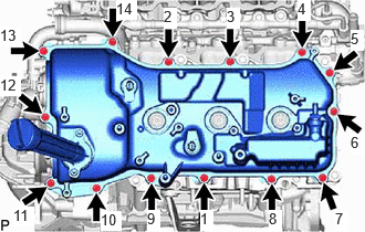
w/ Secondary Air Injection System:
Temporarily install the cylinder head cover sub-assembly LH with the 14 bolts. Tighten the bolts uniformly in several steps.
- Torque:
- 10 N*m (102 kgf*cm, 7 ft.*lbf)
- NOTICE:
-
Do not start the engine for at least 2 hours after installation.
Install the 2 VVT sensors to the cylinder head cover sub-assembly LH.
23224D
16.INSTALL FUEL PUMP SPACER GASKET
23100X
17.TEMPORARILY INSTALL FUEL (ENGINE ROOM SIDE) PUMP ASSEMBLY
23801P
18.TEMPORARILY INSTALL NO. 1 FUEL PIPE SUB-ASSEMBLY
23100X
19.INSTALL FUEL (ENGINE ROOM SIDE) PUMP ASSEMBLY
23801P
20.INSTALL NO. 1 FUEL PIPE SUB-ASSEMBLY
23903
21.INSTALL NO. 3 FUEL TUBE SUB-ASSEMBLY
17111
22.INSTALL INTAKE MANIFOLD
23800
23.INSTALL FUEL DELIVERY WITH SENSOR PIPE ASSEMBLY
88431
24.INSTALL NO. 1 COMPRESSOR MOUNTING BRACKET
16620
25.INSTALL V-RIBBED BELT TENSIONER ASSEMBLY
16604
26.INSTALL NO. 2 IDLER PULLEY SUB-ASSEMBLY
16603
27.INSTALL NO. 1 IDLER PULLEY SUB-ASSEMBLY
15609
28.INSTALL OIL FILTER BRACKET SUB-ASSEMBLY
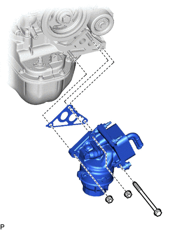
Install the oil filter bracket sub-assembly and a new gasket with the 2 nuts and bolt.
- Torque:
- 21 N*m (214 kgf*cm, 15 ft.*lbf)
16331
29.INSTALL WATER OUTLET
16281
30.INSTALL NO. 4 WATER BY-PASS HOSE
16267
31.INSTALL NO. 3 WATER BY-PASS HOSE
16264
32.INSTALL NO. 2 WATER BY-PASS HOSE
16261
33.INSTALL NO. 1 WATER BY-PASS HOSE
16268
34.INSTALL NO. 1 WATER BY-PASS PIPE
19500
35.INSTALL IGNITION COIL ASSEMBLY
23901
36.INSTALL FUEL TUBE SUB-ASSEMBLY AND NO. 2 FUEL TUBE SUB-ASSEMBLY
12262
37.INSTALL NO. 2 PCV HOSE
12261
38.INSTALL PCV HOSE
12601B
39.INSTALL NO. 1 ENGINE COVER SUB-ASSEMBLY (w/o Secondary Air Injection System)
12601B
40.INSTALL NO. 1 ENGINE COVER SUB-ASSEMBLY (w/o Secondary Air Injection System)
17360G
41.INSTALL AIR TUBE ASSEMBLY (w/ Secondary Air Injection System)
42.INSTALL AIR SWITCHING VALVE ASSEMBLY (w/ Secondary Air Injection System)