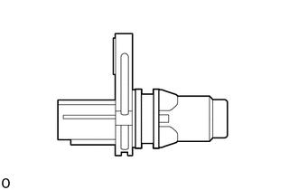
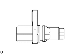
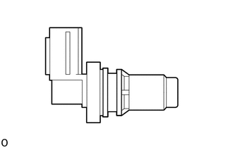
RM35X0E _51 Engine / Hybrid System _078720 7GR-FKS ENGINE CONTROL _0381921 CAMSHAFT POSITION SENSOR A

7GR-FKS ENGINE CONTROL  CAMSHAFT POSITION SENSOR  INSTALLATION  


PROCEDURE

Hide 11401M 1.INSTALL VVT SENSOR (for Exhaust Side of Bank 2)

a.

w/o Secondary Air Injection System:

i.
A527144
2.604,1.375 3.031,1.375 false 1.698,1.083 1.813,0.729 1.813,0.729 2.115,0.729 false 3.083,1.281 3.396,1.479 0.313,0.198 10 false *b 2.188,0.625 2.5,0.823 0.313,0.198 10 false *a
*a Groove
*b VVT Sensor Tip


Perform this procedure only when reusing the VVT sensor.

1.

Clean the O-ring groove of the VVT sensor.

NOTICE:

Make sure the O-ring groove is free of foreign matter.


2.

Install a new O-ring to the VVT sensor.

NOTICE:

Set the O-ring on the tip of the VVT sensor and roll it into the O-ring groove with bare hands to install it.

3.
A407852C09
0.906,1.344 1.031,1.49 1.031,1.49 1.25,1.49 false 2.219,3.156 2.219,2.865 false 2.521,0.49 2.688,0.26 2.688,0.26 2.896,0.26 false 2.521,1.354 2.688,1.479 2.688,1.479 2.927,1.479 false 2.823,2.875 3.104,2.875 false 1.927,2.26 2.208,2.26 false 2.208,1.49 2.208,1.198 false 0.906,2.99 1.031,3.135 1.031,3.135 1.25,3.135 false 0.865,0.667 1.208,0.51 1.208,0.51 1.406,0.51 true 0.865,2.302 1.208,2.146 1.208,2.146 1.406,2.146 true 1.292,1.417 1.604,1.573 0.313,0.156 10 false *1 2.938,0.177 3.146,0.385 0.208,0.208 10 false *c 0.313,0.333 0.625,0.49 0.313,0.156 10 false *a 0.323,2 0.635,2.156 0.313,0.156 10 false *b 0.583,0.854 0.74,1.052 0.156,0.198 10 true A 1.031,0.854 1.188,1.052 0.156,0.198 10 true A 1.031,2.51 1.188,2.708 0.156,0.198 10 true B 0.604,2.51 0.76,2.708 0.156,0.198 10 true B 2.156,1.51 2.469,1.667 0.313,0.156 10 false *1 2.156,3.177 2.469,3.333 0.313,0.156 10 false *1 2.344,0.094 2.802,0.292 0.458,0.198 10 false A - A 2.354,1.875 2.813,2.073 0.458,0.198 10 false B - B 3.135,2.813 3.344,3.021 0.208,0.208 10 false *c 2.969,1.406 3.177,1.615 0.208,0.208 10 false *c 1.75,2.177 1.958,2.385 0.208,0.208 10 false *c 1.281,3.063 1.594,3.219 0.313,0.156 10 false *1 1.448,0.448 1.656,0.656 0.208,0.208 10 false *c 1.438,2.083 1.646,2.292 0.208,0.208 10 false *c
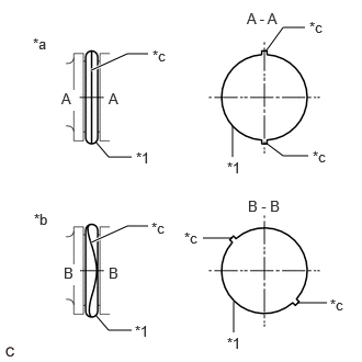
*1 O-ring
*a Correct
*b Incorrect
*c Seam


Check if the O-ring is twisted.

HINT:

Check the entire circumference of the seam of the O-ring for twisting.
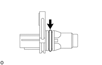


ii.
A527141

Apply a light coat of engine oil to the O-ring of the VVT sensor.
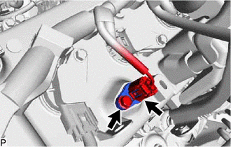

iii.
A443215

Install the VVT sensor to the cylinder head cover sub-assembly LH with the bolt.

Torque:
10 N*m (102 kgf*cm, 7 ft.*lbf)

NOTICE:
·

If the VVT sensor has been struck or dropped, replace it.

·

Make sure that the O-ring is not cracked or moved out of place when installing the VVT sensor.


iv.

Connect the VVT sensor connector.


b.

w/ Secondary Air Injection System:

i.
A527146
2.604,1.375 3.031,1.375 false 1.698,1.083 1.813,0.729 1.813,0.729 2.115,0.729 false 3.083,1.281 3.396,1.479 0.313,0.198 10 false *b 2.188,0.625 2.5,0.823 0.313,0.198 10 false *a
*a Groove
*b VVT Sensor Tip


Perform this procedure only when reusing the VVT sensor.

1.

Clean the O-ring groove of the VVT sensor.

NOTICE:

Make sure the O-ring groove is free of foreign matter.


2.

Install a new O-ring to the VVT sensor.

NOTICE:

Set the O-ring on the tip of the VVT sensor and roll it into the O-ring groove with bare hands to install it.


3.
A407852C09
0.906,1.344 1.031,1.49 1.031,1.49 1.25,1.49 false 2.219,3.156 2.219,2.865 false 2.521,0.49 2.688,0.26 2.688,0.26 2.896,0.26 false 2.521,1.354 2.688,1.479 2.688,1.479 2.927,1.479 false 2.823,2.875 3.104,2.875 false 1.927,2.26 2.208,2.26 false 2.208,1.49 2.208,1.198 false 0.906,2.99 1.031,3.135 1.031,3.135 1.25,3.135 false 0.865,0.667 1.208,0.51 1.208,0.51 1.406,0.51 true 0.865,2.302 1.208,2.146 1.208,2.146 1.406,2.146 true 1.292,1.417 1.604,1.573 0.313,0.156 10 false *1 2.938,0.177 3.146,0.385 0.208,0.208 10 false *c 0.313,0.333 0.625,0.49 0.313,0.156 10 false *a 0.323,2 0.635,2.156 0.313,0.156 10 false *b 0.583,0.854 0.74,1.052 0.156,0.198 10 true A 1.031,0.854 1.188,1.052 0.156,0.198 10 true A 1.031,2.51 1.188,2.708 0.156,0.198 10 true B 0.604,2.51 0.76,2.708 0.156,0.198 10 true B 2.156,1.51 2.469,1.667 0.313,0.156 10 false *1 2.156,3.177 2.469,3.333 0.313,0.156 10 false *1 2.344,0.094 2.802,0.292 0.458,0.198 10 false A - A 2.354,1.875 2.813,2.073 0.458,0.198 10 false B - B 3.135,2.813 3.344,3.021 0.208,0.208 10 false *c 2.969,1.406 3.177,1.615 0.208,0.208 10 false *c 1.75,2.177 1.958,2.385 0.208,0.208 10 false *c 1.281,3.063 1.594,3.219 0.313,0.156 10 false *1 1.448,0.448 1.656,0.656 0.208,0.208 10 false *c 1.438,2.083 1.646,2.292 0.208,0.208 10 false *c
*1 O-ring
*a Correct
*b Incorrect
*c Seam


Check if the O-ring is twisted.

HINT:

Check the entire circumference of the seam of the O-ring for twisting.
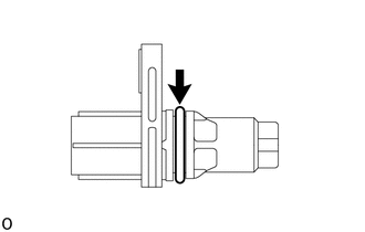


ii.
A527143

Apply a light coat of engine oil to the O-ring of the VVT sensor.
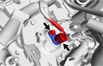

iii.
A443220

Install the VVT sensor to the cylinder head cover sub-assembly LH with the bolt.

Torque:
10 N*m (102 kgf*cm, 7 ft.*lbf)

NOTICE:
·

If the VVT sensor has been struck or dropped, replace it.

·

Make sure that the O-ring is not cracked or moved out of place when installing the VVT sensor.


iv.

Connect the VVT sensor connector.


Hide 11401M 2.INSTALL VVT SENSOR (for Intake Side of Bank 2)

a.

w/o Secondary Air Injection System:

i.
A527144
2.604,1.375 3.031,1.375 false 1.698,1.083 1.813,0.729 1.813,0.729 2.115,0.729 false 3.083,1.281 3.396,1.479 0.313,0.198 10 false *b 2.188,0.625 2.5,0.823 0.313,0.198 10 false *a
*a Groove
*b VVT Sensor Tip


Perform this procedure only when reusing the VVT sensor.

1.

Clean the O-ring groove of the VVT sensor.

NOTICE:

Make sure the O-ring groove is free of foreign matter.


2.

Install a new O-ring to the VVT sensor.

NOTICE:

Set the O-ring on the tip of the VVT sensor and roll it into the O-ring groove with bare hands to install it.


3.
A407852C09
0.906,1.344 1.031,1.49 1.031,1.49 1.25,1.49 false 2.219,3.156 2.219,2.865 false 2.521,0.49 2.688,0.26 2.688,0.26 2.896,0.26 false 2.521,1.354 2.688,1.479 2.688,1.479 2.927,1.479 false 2.823,2.875 3.104,2.875 false 1.927,2.26 2.208,2.26 false 2.208,1.49 2.208,1.198 false 0.906,2.99 1.031,3.135 1.031,3.135 1.25,3.135 false 0.865,0.667 1.208,0.51 1.208,0.51 1.406,0.51 true 0.865,2.302 1.208,2.146 1.208,2.146 1.406,2.146 true 1.292,1.417 1.604,1.573 0.313,0.156 10 false *1 2.938,0.177 3.146,0.385 0.208,0.208 10 false *c 0.313,0.333 0.625,0.49 0.313,0.156 10 false *a 0.323,2 0.635,2.156 0.313,0.156 10 false *b 0.583,0.854 0.74,1.052 0.156,0.198 10 true A 1.031,0.854 1.188,1.052 0.156,0.198 10 true A 1.031,2.51 1.188,2.708 0.156,0.198 10 true B 0.604,2.51 0.76,2.708 0.156,0.198 10 true B 2.156,1.51 2.469,1.667 0.313,0.156 10 false *1 2.156,3.177 2.469,3.333 0.313,0.156 10 false *1 2.344,0.094 2.802,0.292 0.458,0.198 10 false A - A 2.354,1.875 2.813,2.073 0.458,0.198 10 false B - B 3.135,2.813 3.344,3.021 0.208,0.208 10 false *c 2.969,1.406 3.177,1.615 0.208,0.208 10 false *c 1.75,2.177 1.958,2.385 0.208,0.208 10 false *c 1.281,3.063 1.594,3.219 0.313,0.156 10 false *1 1.448,0.448 1.656,0.656 0.208,0.208 10 false *c 1.438,2.083 1.646,2.292 0.208,0.208 10 false *c
*1 O-ring
*a Correct
*b Incorrect
*c Seam


Check if the O-ring is twisted.

HINT:

Check the entire circumference of the seam of the O-ring for twisting.


ii.
A527141

Apply a light coat of engine oil to the O-ring of the VVT sensor.
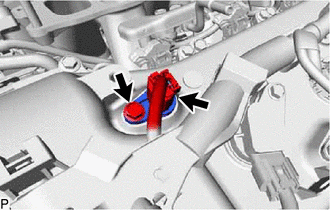

iii.
A443214

Install the VVT sensor to the cylinder head cover sub-assembly LH with the bolt.

Torque:
10 N*m (102 kgf*cm, 7 ft.*lbf)

NOTICE:
·

If the VVT sensor has been struck or dropped, replace it.

·

Make sure that the O-ring is not cracked or moved out of place when installing the VVT sensor.


iv.

Connect the VVT sensor connector.


b.

w/ Secondary Air Injection System:

i.
A527146
2.604,1.375 3.031,1.375 false 1.698,1.083 1.813,0.729 1.813,0.729 2.115,0.729 false 3.083,1.281 3.396,1.479 0.313,0.198 10 false *b 2.188,0.625 2.5,0.823 0.313,0.198 10 false *a
*a Groove
*b VVT Sensor Tip


Perform this procedure only when reusing the VVT sensor.

1.

Clean the O-ring groove of the VVT sensor.

NOTICE:

Make sure the O-ring groove is free of foreign matter.


2.

Install a new O-ring to the VVT sensor.

NOTICE:

Set the O-ring on the tip of the VVT sensor and roll it into the O-ring groove with bare hands to install it.


3.
A407852C09
0.906,1.344 1.031,1.49 1.031,1.49 1.25,1.49 false 2.219,3.156 2.219,2.865 false 2.521,0.49 2.688,0.26 2.688,0.26 2.896,0.26 false 2.521,1.354 2.688,1.479 2.688,1.479 2.927,1.479 false 2.823,2.875 3.104,2.875 false 1.927,2.26 2.208,2.26 false 2.208,1.49 2.208,1.198 false 0.906,2.99 1.031,3.135 1.031,3.135 1.25,3.135 false 0.865,0.667 1.208,0.51 1.208,0.51 1.406,0.51 true 0.865,2.302 1.208,2.146 1.208,2.146 1.406,2.146 true 1.292,1.417 1.604,1.573 0.313,0.156 10 false *1 2.938,0.177 3.146,0.385 0.208,0.208 10 false *c 0.313,0.333 0.625,0.49 0.313,0.156 10 false *a 0.323,2 0.635,2.156 0.313,0.156 10 false *b 0.583,0.854 0.74,1.052 0.156,0.198 10 true A 1.031,0.854 1.188,1.052 0.156,0.198 10 true A 1.031,2.51 1.188,2.708 0.156,0.198 10 true B 0.604,2.51 0.76,2.708 0.156,0.198 10 true B 2.156,1.51 2.469,1.667 0.313,0.156 10 false *1 2.156,3.177 2.469,3.333 0.313,0.156 10 false *1 2.344,0.094 2.802,0.292 0.458,0.198 10 false A - A 2.354,1.875 2.813,2.073 0.458,0.198 10 false B - B 3.135,2.813 3.344,3.021 0.208,0.208 10 false *c 2.969,1.406 3.177,1.615 0.208,0.208 10 false *c 1.75,2.177 1.958,2.385 0.208,0.208 10 false *c 1.281,3.063 1.594,3.219 0.313,0.156 10 false *1 1.448,0.448 1.656,0.656 0.208,0.208 10 false *c 1.438,2.083 1.646,2.292 0.208,0.208 10 false *c
*1 O-ring
*a Correct
*b Incorrect
*c Seam


Check if the O-ring is twisted.

HINT:

Check the entire circumference of the seam of the O-ring for twisting.


ii.
A527143

Apply a light coat of engine oil to the O-ring of the VVT sensor.
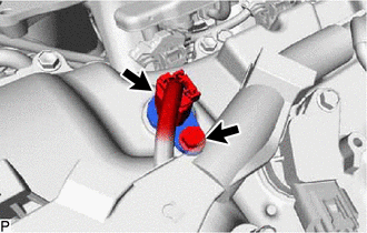

iii.
A443219

Install the VVT sensor to the cylinder head cover sub-assembly LH with the bolt.

Torque:
10 N*m (102 kgf*cm, 7 ft.*lbf)

NOTICE:
·

If the VVT sensor has been struck or dropped, replace it.

·

Make sure that the O-ring is not cracked or moved out of place when installing the VVT sensor.


iv.

Connect the VVT sensor connector.


Hide 11401M 3.INSTALL VVT SENSOR (for Exhaust Side of Bank 1)

a.

w/o Secondary Air Injection System:

i.
A527144
2.604,1.375 3.031,1.375 false 1.698,1.083 1.813,0.729 1.813,0.729 2.115,0.729 false 3.083,1.281 3.396,1.479 0.313,0.198 10 false *b 2.188,0.625 2.5,0.823 0.313,0.198 10 false *a
*a Groove
*b VVT Sensor Tip


Perform this procedure only when reusing the VVT sensor.

1.

Clean the O-ring groove of the VVT sensor.

NOTICE:

Make sure the O-ring groove is free of foreign matter.


2.

Install a new O-ring to the VVT sensor.

NOTICE:

Set the O-ring on the tip of the VVT sensor and roll it into the O-ring groove with bare hands to install it.


3.
A407852C09
0.906,1.344 1.031,1.49 1.031,1.49 1.25,1.49 false 2.219,3.156 2.219,2.865 false 2.521,0.49 2.688,0.26 2.688,0.26 2.896,0.26 false 2.521,1.354 2.688,1.479 2.688,1.479 2.927,1.479 false 2.823,2.875 3.104,2.875 false 1.927,2.26 2.208,2.26 false 2.208,1.49 2.208,1.198 false 0.906,2.99 1.031,3.135 1.031,3.135 1.25,3.135 false 0.865,0.667 1.208,0.51 1.208,0.51 1.406,0.51 true 0.865,2.302 1.208,2.146 1.208,2.146 1.406,2.146 true 1.292,1.417 1.604,1.573 0.313,0.156 10 false *1 2.938,0.177 3.146,0.385 0.208,0.208 10 false *c 0.313,0.333 0.625,0.49 0.313,0.156 10 false *a 0.323,2 0.635,2.156 0.313,0.156 10 false *b 0.583,0.854 0.74,1.052 0.156,0.198 10 true A 1.031,0.854 1.188,1.052 0.156,0.198 10 true A 1.031,2.51 1.188,2.708 0.156,0.198 10 true B 0.604,2.51 0.76,2.708 0.156,0.198 10 true B 2.156,1.51 2.469,1.667 0.313,0.156 10 false *1 2.156,3.177 2.469,3.333 0.313,0.156 10 false *1 2.344,0.094 2.802,0.292 0.458,0.198 10 false A - A 2.354,1.875 2.813,2.073 0.458,0.198 10 false B - B 3.135,2.813 3.344,3.021 0.208,0.208 10 false *c 2.969,1.406 3.177,1.615 0.208,0.208 10 false *c 1.75,2.177 1.958,2.385 0.208,0.208 10 false *c 1.281,3.063 1.594,3.219 0.313,0.156 10 false *1 1.448,0.448 1.656,0.656 0.208,0.208 10 false *c 1.438,2.083 1.646,2.292 0.208,0.208 10 false *c
*1 O-ring
*a Correct
*b Incorrect
*c Seam


Check if the O-ring is twisted.

HINT:

Check the entire circumference of the seam of the O-ring for twisting.


ii.
A527141

Apply a light coat of engine oil to the O-ring of the VVT sensor.
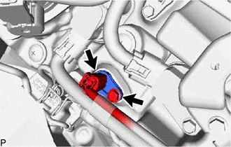

iii.
A443213

Install the VVT sensor to the cylinder head cover sub-assembly with the bolt.

Torque:
10 N*m (102 kgf*cm, 7 ft.*lbf)

NOTICE:
·

If the VVT sensor has been struck or dropped, replace it.

·

Make sure that the O-ring is not cracked or moved out of place when installing the VVT sensor.


iv.

Connect the VVT sensor connector.


b.

w/ Secondary Air Injection System:

i.
A527146
2.604,1.375 3.031,1.375 false 1.698,1.083 1.813,0.729 1.813,0.729 2.115,0.729 false 3.083,1.281 3.396,1.479 0.313,0.198 10 false *b 2.188,0.625 2.5,0.823 0.313,0.198 10 false *a
*a Groove
*b VVT Sensor Tip


Perform this procedure only when reusing the VVT sensor.

1.

Clean the O-ring groove of the VVT sensor.

NOTICE:

Make sure the O-ring groove is free of foreign matter.


2.

Install a new O-ring to the VVT sensor.

NOTICE:

Set the O-ring on the tip of the VVT sensor and roll it into the O-ring groove with bare hands to install it.


3.
A407852C09
0.906,1.344 1.031,1.49 1.031,1.49 1.25,1.49 false 2.219,3.156 2.219,2.865 false 2.521,0.49 2.688,0.26 2.688,0.26 2.896,0.26 false 2.521,1.354 2.688,1.479 2.688,1.479 2.927,1.479 false 2.823,2.875 3.104,2.875 false 1.927,2.26 2.208,2.26 false 2.208,1.49 2.208,1.198 false 0.906,2.99 1.031,3.135 1.031,3.135 1.25,3.135 false 0.865,0.667 1.208,0.51 1.208,0.51 1.406,0.51 true 0.865,2.302 1.208,2.146 1.208,2.146 1.406,2.146 true 1.292,1.417 1.604,1.573 0.313,0.156 10 false *1 2.938,0.177 3.146,0.385 0.208,0.208 10 false *c 0.313,0.333 0.625,0.49 0.313,0.156 10 false *a 0.323,2 0.635,2.156 0.313,0.156 10 false *b 0.583,0.854 0.74,1.052 0.156,0.198 10 true A 1.031,0.854 1.188,1.052 0.156,0.198 10 true A 1.031,2.51 1.188,2.708 0.156,0.198 10 true B 0.604,2.51 0.76,2.708 0.156,0.198 10 true B 2.156,1.51 2.469,1.667 0.313,0.156 10 false *1 2.156,3.177 2.469,3.333 0.313,0.156 10 false *1 2.344,0.094 2.802,0.292 0.458,0.198 10 false A - A 2.354,1.875 2.813,2.073 0.458,0.198 10 false B - B 3.135,2.813 3.344,3.021 0.208,0.208 10 false *c 2.969,1.406 3.177,1.615 0.208,0.208 10 false *c 1.75,2.177 1.958,2.385 0.208,0.208 10 false *c 1.281,3.063 1.594,3.219 0.313,0.156 10 false *1 1.448,0.448 1.656,0.656 0.208,0.208 10 false *c 1.438,2.083 1.646,2.292 0.208,0.208 10 false *c
*1 O-ring
*a Correct
*b Incorrect
*c Seam


Check if the O-ring is twisted.

HINT:

Check the entire circumference of the seam of the O-ring for twisting.


ii.
A527143

Apply a light coat of engine oil to the O-ring of the VVT sensor.
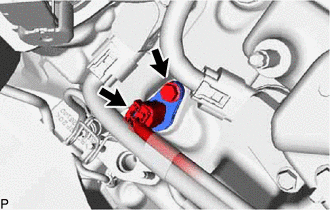

iii.
A443218

Install the VVT sensor to the cylinder head cover sub-assembly with the bolt.

Torque:
10 N*m (102 kgf*cm, 7 ft.*lbf)

NOTICE:
·

If the VVT sensor has been struck or dropped, replace it.

·

Make sure that the O-ring is not cracked or moved out of place when installing the VVT sensor.


iv.

Connect the VVT sensor connector.


Hide 11401Q 4.INSTALL VVT SENSOR (for Intake Side of Bank 1)

a.

w/o Secondary Air Injection System:

i.
A527145
2.625,1.375 3.052,1.375 false 1.646,1.073 1.76,0.719 1.76,0.719 2.063,0.719 false 3.083,1.281 3.396,1.479 0.313,0.198 10 false *b 2.094,0.625 2.406,0.823 0.313,0.198 10 false *a
*a Groove
*b VVT Sensor Tip


Perform this procedure only when reusing the VVT sensor.

1.

Clean the O-ring groove of the VVT sensor.

NOTICE:

Make sure the O-ring groove is free of foreign matter.


2.

Install a new O-ring to the VVT sensor.

NOTICE:

Set the O-ring on the tip of the VVT sensor and roll it into the O-ring groove with bare hands to install it.


3.
A407852C09
0.906,1.344 1.031,1.49 1.031,1.49 1.25,1.49 false 2.219,3.156 2.219,2.865 false 2.521,0.49 2.688,0.26 2.688,0.26 2.896,0.26 false 2.521,1.354 2.688,1.479 2.688,1.479 2.927,1.479 false 2.823,2.875 3.104,2.875 false 1.927,2.26 2.208,2.26 false 2.208,1.49 2.208,1.198 false 0.906,2.99 1.031,3.135 1.031,3.135 1.25,3.135 false 0.865,0.667 1.208,0.51 1.208,0.51 1.406,0.51 true 0.865,2.302 1.208,2.146 1.208,2.146 1.406,2.146 true 1.292,1.417 1.604,1.573 0.313,0.156 10 false *1 2.938,0.177 3.146,0.385 0.208,0.208 10 false *c 0.313,0.333 0.625,0.49 0.313,0.156 10 false *a 0.323,2 0.635,2.156 0.313,0.156 10 false *b 0.583,0.854 0.74,1.052 0.156,0.198 10 true A 1.031,0.854 1.188,1.052 0.156,0.198 10 true A 1.031,2.51 1.188,2.708 0.156,0.198 10 true B 0.604,2.51 0.76,2.708 0.156,0.198 10 true B 2.156,1.51 2.469,1.667 0.313,0.156 10 false *1 2.156,3.177 2.469,3.333 0.313,0.156 10 false *1 2.344,0.094 2.802,0.292 0.458,0.198 10 false A - A 2.354,1.875 2.813,2.073 0.458,0.198 10 false B - B 3.135,2.813 3.344,3.021 0.208,0.208 10 false *c 2.969,1.406 3.177,1.615 0.208,0.208 10 false *c 1.75,2.177 1.958,2.385 0.208,0.208 10 false *c 1.281,3.063 1.594,3.219 0.313,0.156 10 false *1 1.448,0.448 1.656,0.656 0.208,0.208 10 false *c 1.438,2.083 1.646,2.292 0.208,0.208 10 false *c
*1 O-ring
*a Correct
*b Incorrect
*c Seam


Check if the O-ring is twisted.

HINT:

Check the entire circumference of the seam of the O-ring for twisting.


ii.
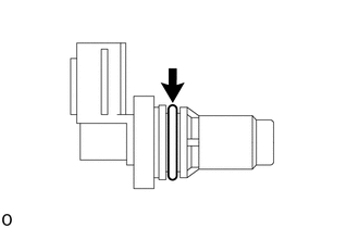
A527142

Apply a light coat of engine oil to the O-ring of the VVT sensor.

iii.
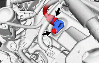
A443212

Install the VVT sensor to the cylinder head cover sub-assembly with the bolt.

Torque:
10 N*m (102 kgf*cm, 7 ft.*lbf)

NOTICE:
·

If the VVT sensor has been struck or dropped, replace it.

·

Make sure that the O-ring is not cracked or moved out of place when installing the VVT sensor.


iv.

Connect the VVT sensor connector.


b.

w/ Secondary Air Injection System:

i.
A527146
2.604,1.375 3.031,1.375 false 1.698,1.083 1.813,0.729 1.813,0.729 2.115,0.729 false 3.083,1.281 3.396,1.479 0.313,0.198 10 false *b 2.188,0.625 2.5,0.823 0.313,0.198 10 false *a
*a Groove
*b VVT Sensor Tip


Perform this procedure only when reusing the VVT sensor.

1.

Clean the O-ring groove of the VVT sensor.

NOTICE:

Make sure the O-ring groove is free of foreign matter.


2.

Install a new O-ring to the VVT sensor.

NOTICE:

Set the O-ring on the tip of the VVT sensor and roll it into the O-ring groove with bare hands to install it.


3.
A407852C09
0.906,1.344 1.031,1.49 1.031,1.49 1.25,1.49 false 2.219,3.156 2.219,2.865 false 2.521,0.49 2.688,0.26 2.688,0.26 2.896,0.26 false 2.521,1.354 2.688,1.479 2.688,1.479 2.927,1.479 false 2.823,2.875 3.104,2.875 false 1.927,2.26 2.208,2.26 false 2.208,1.49 2.208,1.198 false 0.906,2.99 1.031,3.135 1.031,3.135 1.25,3.135 false 0.865,0.667 1.208,0.51 1.208,0.51 1.406,0.51 true 0.865,2.302 1.208,2.146 1.208,2.146 1.406,2.146 true 1.292,1.417 1.604,1.573 0.313,0.156 10 false *1 2.938,0.177 3.146,0.385 0.208,0.208 10 false *c 0.313,0.333 0.625,0.49 0.313,0.156 10 false *a 0.323,2 0.635,2.156 0.313,0.156 10 false *b 0.583,0.854 0.74,1.052 0.156,0.198 10 true A 1.031,0.854 1.188,1.052 0.156,0.198 10 true A 1.031,2.51 1.188,2.708 0.156,0.198 10 true B 0.604,2.51 0.76,2.708 0.156,0.198 10 true B 2.156,1.51 2.469,1.667 0.313,0.156 10 false *1 2.156,3.177 2.469,3.333 0.313,0.156 10 false *1 2.344,0.094 2.802,0.292 0.458,0.198 10 false A - A 2.354,1.875 2.813,2.073 0.458,0.198 10 false B - B 3.135,2.813 3.344,3.021 0.208,0.208 10 false *c 2.969,1.406 3.177,1.615 0.208,0.208 10 false *c 1.75,2.177 1.958,2.385 0.208,0.208 10 false *c 1.281,3.063 1.594,3.219 0.313,0.156 10 false *1 1.448,0.448 1.656,0.656 0.208,0.208 10 false *c 1.438,2.083 1.646,2.292 0.208,0.208 10 false *c
*1 O-ring
*a Correct
*b Incorrect
*c Seam


Check if the O-ring is twisted.

HINT:

Check the entire circumference of the seam of the O-ring for twisting.


ii.
A527143

Apply a light coat of engine oil to the O-ring of the VVT sensor.

iii.
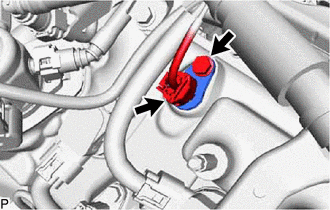
A443217

Install the VVT sensor to the cylinder head cover sub-assembly with the bolt.

Torque:
10 N*m (102 kgf*cm, 7 ft.*lbf)

NOTICE:
·

If the VVT sensor has been struck or dropped, replace it.

·

Make sure that the O-ring is not cracked or moved out of place when installing the VVT sensor.


iv.

Connect the VVT sensor connector.