CRUISE CONTROL CRUISE CONTROL SYSTEM Cruise SET Indicator Light Circuit
DESCRIPTION
The ECM illuminates the cruise SET indicator by sending indicator output demand signals to the combination meter assembly via CAN communication. The cruise SET indicator illuminates when the cruise control system is controlling vehicle speed. The cruise SET indicator light circuit uses CAN communication. If the cruise SET indicator is not functioning correctly, check for CAN communication DTCs before troubleshooting this circuit.
CAUTION / NOTICE / HINT
- CAUTION:
-
Observe the following items for safety reasons when using the GTS:
- ·
Before using the GTS, read the instruction manual.
·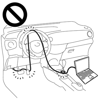
Prevent the GTS cable from being caught on the pedals, shift lever or steering wheel when driving with the GTS connected to the vehicle.
·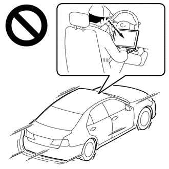
When driving the vehicle for testing purposes, 2 people are required. One person should operate the GTS while the other drives the vehicle.
- NOTICE:
-
When replacing the combination meter assembly, always replace it with a new one. If a combination meter assembly which was installed to another vehicle is used, the information stored in it will not match the information from the vehicle and a DTC may be stored.
PROCEDURE
Connect the GTS to the DLC3.
Turn the ignition switch to ON.
Turn the GTS on.
Enter the following menus: Body Electrical / Combination Meter / Active Test.
Perform "Active Test" according to the display on the GTS.
- Body Electrical > Combination Meter > Active Test
-
Tester Display Measurement Item Control Range Diagnostic Note Multi Display All (White) Multi-information display (White display) ON -
- Body Electrical > Combination Meter > Active Test
-
Tester Display Multi Display All (White) - 50004 409 20
- Result:
Result Proceed to The multi-information display in the combination meter assembly turns on according to the operation of the Active Test. A The multi-information display in the combination meter assembly does not turn on according to the operation of the Active Test. B
A
B
Turn the cruise control system on using the cruise control main switch.
Drive at a speed between approximately 30 km/h (20 mph) and 200 km/h (125 mph).
Enter the following menus: Powertrain / Cruise Control / Data List.
Read the Data List according to the display on the GTS.
except 1GD-FTV (Urea SCR System):
- Powertrain > Cruise Control > Data List
-
Tester Display Measurement Item Range Normal Condition Diagnostic Note -SET Switch -SET switch signal ON or OFF ON: -SET switch pushed
OFF: -SET switch not pushed-
- Powertrain > Cruise Control > Data List
-
Tester Display -SET Switch - 50003 374 19
for 1GD-FTV (Urea SCR System):
- Powertrain > Cruise Control > Data List
-
Tester Display Measurement Item Range Normal Condition Diagnostic Note -SET Switch -SET switch signal ON or OFF ON: -SET switch pushed
OFF: -SET switch not pushed-
- Powertrain > Cruise Control > Data List
-
Tester Display -SET Switch - 50003 457 19
- Result:
Result Proceed to The cruise SET indicator illuminates and turns off according to the operation of the -SET switch. A The cruise SET indicator does not illuminate but the Data List item -SET Switch changes according to the operation of the -SET switch. B The cruise SET indicator does not illuminate and the Data List item -SET Switch does not change according to the operation of the -SET switch. C
A
B
C