PARK ASSIST / MONITORING PARKING ASSIST MONITOR SYSTEM C1625 Open or Short in Steering Angle Sensor +B
DESCRIPTION
This DTC is stored if the television camera assembly receives a signal via CAN communication from the steering sensor that indicates a power supply problem.
| DTC No. | Detection Item | DTC Detection Condition | Trouble Area |
|---|---|---|---|
| C1625 | Open or Short in Steering Angle Sensor +B | Open or short in steering sensor power source | ·
Harness or connector ·
Steering sensor |
WIRING DIAGRAM
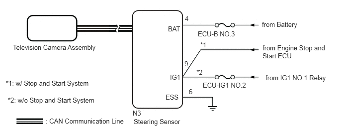
CAUTION / NOTICE / HINT
- NOTICE:
- ·
When the "!" mark is displayed on the radio and display receiver assembly after disconnecting the cable from the negative (-) battery terminal, correct the steering angle neutral point.
·Depending on the parts that are replaced or operations that are performed during vehicle inspection or maintenance, calibration of other systems as well as the parking assist monitor system may be needed.
·The vehicle is equipped with a Supplemental Restraint System (SRS) which includes components such as airbags. Before servicing (including removal or installation of parts), be sure to read the precaution for Supplemental Restraint System.
for Type A:
for Type B:
for Type C:
·After turning the ignition switch off, waiting time may be required before disconnecting the cable from the negative (-) battery terminal.
·When disconnecting the cable from the negative (-) battery terminal while performing repairs, some systems need to be initialized after the cable is reconnected.
- HINT:
-
When disconnecting and reconnecting the battery, there is an automatic learning function that completes learning when the respective system is used.
·Inspect the fuses for circuits related to this system before performing the following procedure.
PROCEDURE
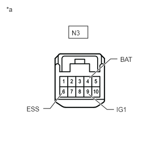
| *a | Front view of wire harness connector
(to Steering Sensor) |
Disconnect the steering sensor connector.
Measure the resistance according to the value(s) in the table below.
- Standard Resistance:
Tester Connection Condition Specified Condition N3-6 (ESS) - Body ground Always Below 1 Ω
Measure the voltage according to the value(s) in the table below.
- Standard Voltage:
Tester Connection Switch Condition Specified Condition *1: w/o Stop and Start System
*2: w/ Stop and Start System
N3-9 (IG1) - N3-6 (ESS) Ignition switch ON 11 to 14 V*1
10.5 to 16 V*2N3-4 (BAT) - N3-6 (ESS) Ignition switch off 11 to 14 V
- Result:
Result Proceed to OK A NG (w/o Stop and Start System) B NG (w/ Stop and Start System) C
A
B
C