7GR-FKS COOLING RADIATOR INSTALLATION
CAUTION / NOTICE / HINT
- HINT:
- ·
Use the same procedure for RHD and LHD vehicles.
·The procedure listed below is for LHD vehicles.
PROCEDURE

 16535
1.INSTALL LOWER RADIATOR SUPPORT
16535
1.INSTALL LOWER RADIATOR SUPPORT
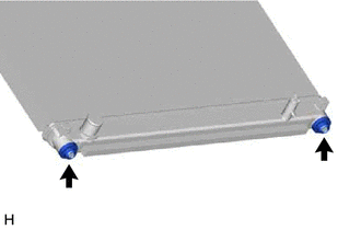
Install the 2 lower radiator supports to the radiator assembly.
16523A
2.INSTALL RADIATOR SUPPORT CUSHION
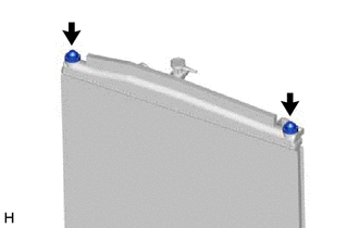
Install the 2 radiator support cushions to the radiator assembly.
16400
3.INSTALL RADIATOR ASSEMBLY
w/ Air Conditioning System:
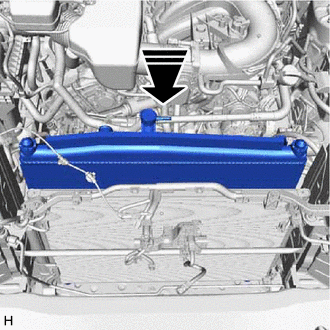

|
Install in this Direction |
Install the radiator assembly to the vehicle as shown in the illustration.
- NOTICE:
- ·
Perform the following procedure with 2 or more people to prevent damage to the radiator assembly.
·When installing the radiator assembly, do not damage the cooler condenser assembly.
w/o Air Conditioning System:
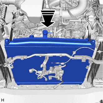
|
|
Install in this Direction |
Install the radiator assembly to the vehicle as shown in the illustration.
- NOTICE:
-
Perform the following procedure with 2 or more people to prevent damage to the radiator assembly.
32922A
4.CONNECT OIL COOLER OUTLET HOSE (for Automatic Transmission)
Connect the oil cooler outlet hose to the radiator assembly, and slide the clip to secure the hose.
- NOTICE:
-
Make sure the oil cooler outlet hose is securely inserted to the stopper.
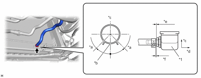
| *1 | Radiator Assembly | - | - |
| *a | 45° | *b | Paint Mark |
| *c | Upper Side | *d | Front Side |
| *e | 0 to 3 mm (0 to 0.118 in.) | *f | 2 to 5 mm (0.0787 to 0.197 in.) |
32921D
5.CONNECT OIL COOLER INLET HOSE (for Automatic Transmission)
Connect the oil cooler inlet hose to the radiator assembly, and slide the clip to secure the hose.
- NOTICE:
-
Make sure the oil cooler inlet hose is securely inserted to the stopper.
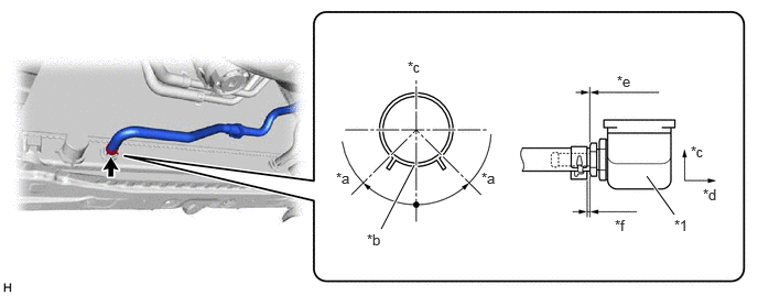
| *1 | Radiator Assembly | - | - |
| *a | 45° | *b | Paint Mark |
| *c | Upper Side | *d | Front Side |
| *e | 0 to 3 mm (0 to 0.118 in.) | *f | 2 to 5 mm (0.0787 to 0.197 in.) |
53205
6.INSTALL UPPER RADIATOR SUPPORT SUB-ASSEMBLY
for LHD:
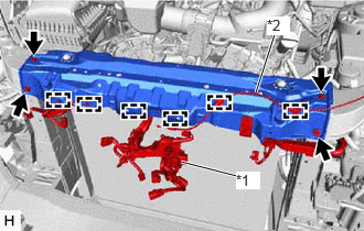
| *1 | Engine Room Main Wire |
| *2 | Hood Lock Control Cable Assembly |
Attach the clamps to connect the engine room main wire and hood lock control cable assembly.
Install the upper radiator support sub-assembly with the 4 bolts.
- Torque:
- 24 N*m (245 kgf*cm, 18 ft.*lbf)
for RHD:
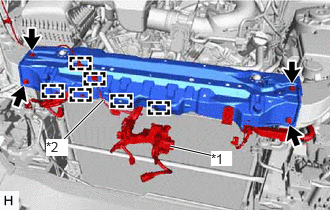
| *1 | Engine Room Main Wire |
| *2 | Hood Lock Control Cable Assembly |
Attach the clamps to connect the engine room main wire and hood lock control cable assembly.
Install the upper radiator support sub-assembly with the 4 bolts.
- Torque:
- 24 N*m (245 kgf*cm, 18 ft.*lbf)
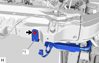
| *1 | Engine Room Main Wire |
Install the bolt to connect the engine room main wire.
- Torque:
- 11.5 N*m (117 kgf*cm, 8 ft.*lbf)
86510
7.INSTALL HIGH PITCHED HORN ASSEMBLY (for 2-piece Type)
86520
8.INSTALL LOW PITCHED HORN ASSEMBLY
51466
9.INSTALL UPPER RADIATOR SUPPORT BRACE LH (for Wagon)
51465
10.INSTALL UPPER RADIATOR SUPPORT BRACE RH (for Wagon)
16546
11.INSTALL RADIATOR PROTECTOR (w/o Air Conditioning System)
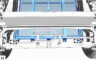
Attach the guides to install the radiator protector.
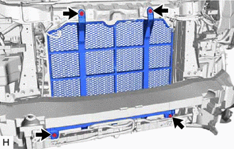
Install the 4 bolts.
- Torque:
- 7.5 N*m (76 kgf*cm, 66 in.*lbf)
52139E
12.INSTALL CENTER FRONT BUMPER BRACE (w/o Air Conditioning System)
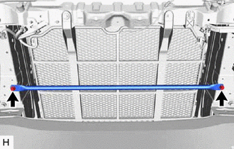
Install the center front bumper brace with the 2 bolts.
- Torque:
- 15 N*m (153 kgf*cm, 11 ft.*lbf)
53285N
13.INSTALL RADIATOR SIDE AIR SEAL RH (w/o Air Conditioning System, for Wagon)
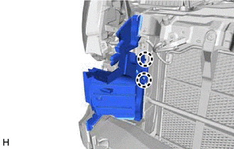
Attach the claws to install the radiator side air seal RH.
53286F
14.INSTALL RADIATOR SIDE AIR SEAL LH (w/o Air Conditioning System, for Wagon)
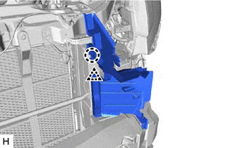
Attach the claw and clip to install the radiator side air seal LH.
53209B
15.INSTALL HOOD LOCK SUPPORT BRACE SUB-ASSEMBLY
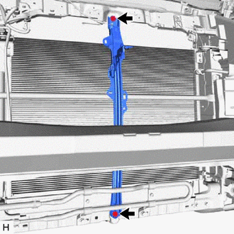
Install the hood lock support brace sub-assembly with the 2 bolts.
- Torque:
- 8.5 N*m (87 kgf*cm, 75 in.*lbf)
w/ Air Conditioning System:
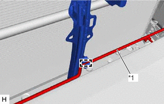
| *1 | Air Conditioner Tube and Accessory Assembly |
Attach the clamp to connect the air conditioner tube and accessory assembly.
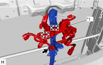
| *1 | Engine Room Main Wire |
Attach the clamps to connect the engine room main wire.
Connect the connector.
53510
16.INSTALL HOOD LOCK ASSEMBLY
17.INSTALL FRONT BUMPER
16711
18.INSTALL FAN SHROUD
Install the fan pulley to the water pump assembly.
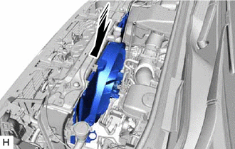
|
|
Install in this Direction |
Place the fan shroud together with the fan with fluid coupling assembly between the engine and radiator assembly.
- NOTICE:
-
Do not allow the radiator assembly to interfere with other parts.
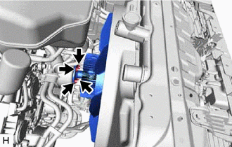
Temporarily install the fan with fluid coupling assembly to the water pump assembly with the 4 nuts.
- NOTICE:
- ·
Make sure to match the paint mark colors on the fan with fluid coupling assembly with the stud bolts of the same color on the water pump assembly.
·When installing the fan and fan and generator V belt, make sure to securely tighten the nuts of the fan with fluid coupling assembly so that the fan pulley is properly aligned.
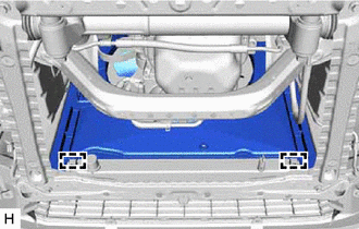
Attach the guides to install the fan shroud.
for Automatic Transmission:
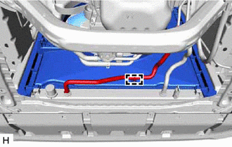
Attach the clamp to connect the oil cooler inlet hose.
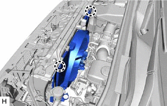
Attach the claws.
Install the fan and generator V belt.
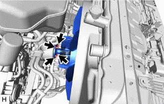
Tighten the 4 nuts holding the fan with fluid coupling assembly.
- Torque:
- 21 N*m (214 kgf*cm, 15 ft.*lbf)
16572D
19.INSTALL NO. 2 RADIATOR HOSE
Attach the clamp to install the No. 2 radiator hose.
Connect the No. 2 radiator hose to the radiator assembly, and slide the clip to secure the hose.
- NOTICE:
- ·
Make sure the No. 2 radiator hose is securely inserted to the stopper.
·Position the clip so that it is 2 to 5 mm (0.0787 to 0.197 in.) away from the end of the water hose.
·Install so that the No. 2 radiator hose paint mark is aligned with the protrusion of the radiator assembly.
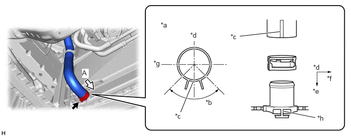
| *a | View A | *b | 90° |
| *c | Paint Mark | *d | Upper Side |
| *e | Front Side | *f | RH Side |
| *g | LH Side | *h | Protrusion of the Radiator Assembly |
Connect the No. 2 radiator hose to the water inlet sub-assembly with thermostat, and slide the clip to secure the hose.
- NOTICE:
- ·
Make sure the No. 2 radiator hose is securely inserted to the stopper.
·Position the clip so that it is 2 to 5 mm (0.0787 to 0.197 in.) away from the end of the water hose.
·Install so that the No. 2 radiator hose paint mark is aligned with the protrusion of the water inlet sub-assembly with thermostat.

| *a | View A | *b | 90° |
| *c | Paint Mark | *d | Upper Side |
| *e | Front Side | *f | RH Side |
| *g | Protrusion of the Water Inlet Sub-assembly with Thermostat | - | - |
16571C
20.INSTALL NO. 1 RADIATOR HOSE
Install the No. 1 radiator hose to the water outlet, and slide the clip to secure the hose.
- NOTICE:
- ·
Make sure the No. 1 radiator hose is securely inserted to the stopper.
·Position the clip so that it is 2 to 5 mm (0.0787 to 0.197 in.) away from the end of the water hose.
·Install so that the No. 1 radiator hose paint mark is aligned with the protrusion of the water outlet.
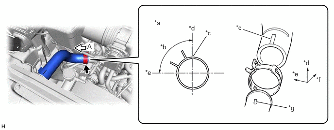
| *a | View A | *b | 90° |
| *c | Paint Mark | *d | Upper Side |
| *e | Front Side | *f | RH Side |
| *g | Protrusion of the Water Outlet | - | - |
Connect the No. 1 radiator hose to the radiator assembly, and slide the clip to secure the hose.
- NOTICE:
- ·
Make sure the No. 1 radiator hose is securely inserted to the stopper.
·Position the clip so that it is 2 to 5 mm (0.0787 to 0.197 in.) away from the end of the water hose.
·Install so that the No. 1 radiator hose paint mark is aligned with the protrusion of the radiator assembly.
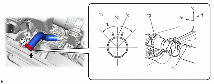
| *a | View A | *b | 90° |
| *c | Paint Mark | *d | Upper Side |
| *e | Front Side | *f | RH Side |
| *g | Protrusion of the Radiator Assembly | - | - |
16470
21.INSTALL RADIATOR RESERVE TANK ASSEMBLY
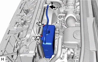

|
Radiator Reserve Tank Hose |

|
Bolt |
Install the radiator reserve tank assembly with the 2 bolts.
- Torque:
- 5.0 N*m (51 kgf*cm, 44 in.*lbf)
Connect the radiator reserve tank hose.
44360
22.CONNECT VANE PUMP OIL RESERVOIR ASSEMBLY
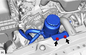
Install the 2 bolts to connect the vane pump oil reservoir assembly.
- Torque:
- 4.5 N*m (46 kgf*cm, 40 in.*lbf)
17751
23.INSTALL NO. 1 AIR CLEANER INLET
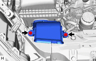
Install the No. 1 air cleaner inlet with the 2 bolts.
- Torque:
- 5.0 N*m (51 kgf*cm, 44 in.*lbf)
53106B
24.INSTALL RADIATOR COVER SUB-ASSEMBLY
11209
25.INSTALL V-BANK COVER SUB-ASSEMBLY (w/ Cover)
26.ADD ENGINE COOLANT
27.INSPECT FOR COOLANT LEAK
51405A
28.INSTALL NO. 1 ENGINE UNDER COVER SUB-ASSEMBLY
52618
29.INSTALL LOWER FRONT BUMPER ABSORBER
51406A
30.INSTALL NO. 2 ENGINE UNDER COVER SUB-ASSEMBLY (w/ No. 2 Engine Under Cover Sub-assembly)