RM35X0E _58 Vehicle Interior _079316 HEATING / AIR CONDITIONING _0386651 AIR CONDITIONING SYSTEM(for Automatic Air Conditioning System) J

HEATING / AIR CONDITIONING  AIR CONDITIONING SYSTEM(for Automatic Air Conditioning System)  Operation not Accepted Even If Air Conditioning Switch is Operated  


DESCRIPTION

If the air conditioning system does not operate even when the air conditioning control assembly is operated, the following causes are possible.

Malfunction Status Factor
Operations are never accepted by the air conditioning control assembly. (With the exception of the switch indicator, everything is turned off.)
·

LIN communication malfunction between air conditioning amplifier assembly and air conditioning control assembly

·

Air conditioning amplifier assembly malfunction (+B or GND circuit)

·

Air conditioning control assembly malfunction (for Front)

·

Air conditioning control assembly malfunction (for Rear (w/ Integration Control Panel))


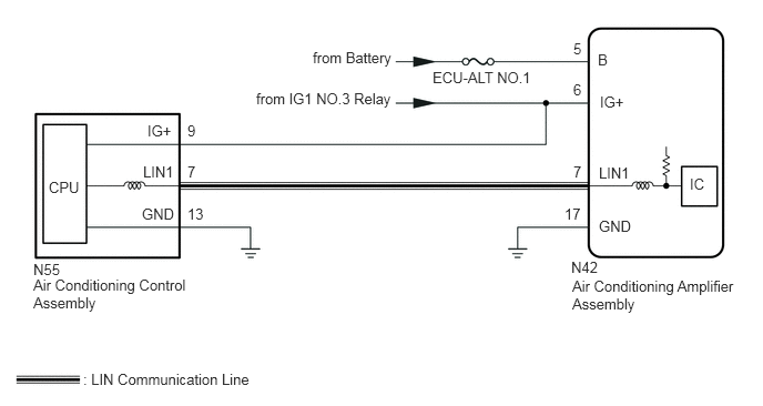
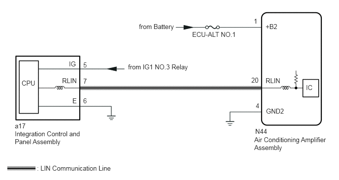
WIRING DIAGRAM

for Front:
E416665E01
5.615,0.479 6.073,0.677 0.458,0.198 10 false B 5.625,1.542 6.083,1.74 0.458,0.198 10 false LIN1 5.625,2.042 6.083,2.24 0.458,0.198 10 false GND 5.365,2.427 5.823,2.625 0.458,0.198 10 false N42 6.479,1.646 6.771,1.844 0.292,0.198 10 false IC 5.375,2.604 6.948,3.115 1.573,0.51 10 false Air Conditioning Amplifier Assembly 5.385,0.375 5.844,0.573 0.458,0.198 10 false 5 5.385,1.531 5.844,1.729 0.458,0.198 10 false 7 5.302,1.927 5.76,2.125 0.458,0.198 10 false 17 1.76,1.146 2.219,1.344 0.458,0.198 10 false 9 1.76,1.531 2.219,1.729 0.458,0.198 10 false 7 1.76,1.927 2.219,2.125 0.458,0.198 10 false 13 1.385,1.146 1.844,1.344 0.458,0.198 10 false IG+ 1.344,1.531 1.802,1.729 0.458,0.198 10 false LIN1 1.333,1.927 1.792,2.125 0.458,0.198 10 false GND 0.458,1.677 0.917,1.875 0.458,0.198 10 false CPU 0.313,2.448 0.771,2.646 0.458,0.198 10 false N55 0.313,2.594 1.802,2.979 1.49,0.385 10 false Air Conditioning Control Assembly 0.781,3.479 2.823,3.677 2.042,0.198 10 false : LIN Communication Line 2.406,0.844 3.969,1.063 1.563,0.219 10 false from IG1 NO.3 Relay 4.063,0.646 5.073,0.854 1.01,0.208 10 false ECU-ALT NO.1 2.938,0.458 3.813,0.667 0.875,0.208 10 false from Battery 5.635,0.875 6.094,1.073 0.458,0.198 10 false IG+ 5.385,0.76 5.844,0.958 0.458,0.198 10 false 6

for Rear (w/ Integration Control Panel):
E418838E01
5.615,0.479 6.073,0.677 0.458,0.198 10 false +B2 5.615,1.625 6.073,1.823 0.458,0.198 10 false RLIN 5.625,2.271 6.083,2.469 0.458,0.198 10 false GND2 6.469,1.771 6.76,1.969 0.292,0.198 10 false IC 5.375,2.875 6.948,3.385 1.573,0.51 10 false Air Conditioning Amplifier Assembly 5.365,0.365 5.823,0.563 0.458,0.198 10 false 1 5.313,1.615 5.771,1.813 0.458,0.198 10 false 20 5.406,2.156 5.865,2.354 0.458,0.198 10 false 4 1.76,1.292 2.219,1.49 0.458,0.198 10 false 5 1.76,1.635 2.219,1.833 0.458,0.198 10 false 7 1.76,2.052 2.219,2.25 0.458,0.198 10 false 6 1.458,1.271 1.917,1.469 0.458,0.198 10 false IG 1.313,1.625 1.771,1.823 0.458,0.198 10 false RLIN 1.531,2.052 1.99,2.25 0.458,0.198 10 false E 0.458,1.677 0.917,1.875 0.458,0.198 10 false CPU 0.313,2.583 0.771,2.781 0.458,0.198 10 false a17 0.313,2.75 1.781,3.146 1.469,0.396 10 false Integration Control and Panel Assembly 0.781,3.479 2.823,3.677 2.042,0.198 10 false : LIN Communication Line 2.708,1.333 4.271,1.552 1.563,0.219 10 false from IG1 NO.3 Relay 4.063,0.646 5.073,0.854 1.01,0.208 10 false ECU-ALT NO.1 2.938,0.479 3.813,0.688 0.875,0.208 10 false from Battery 5.396,2.698 5.854,2.896 0.458,0.198 10 false N44

CAUTION / NOTICE / HINT

NOTICE:

Inspect the fuses and relays for circuits related to this system before performing the following procedure.


PROCEDURE

1.CHECK MALFUNCTION STATUS
Result:
Result Proceed to
for Front A
for Rear (w/ Integration Control Panel) B


A

2.CHECK FOR DTC

B

4.CHECK FOR DTC
2.CHECK FOR DTC
a.

Result:
Proceed to
OK
NG


OK

3.CHECK HARNESS AND CONNECTOR (AIR CONDITIONING AMPLIFIER ASSEMBLY - BATTERY AND BODY GROUND)

NG

3.CHECK HARNESS AND CONNECTOR (AIR CONDITIONING AMPLIFIER ASSEMBLY - BATTERY AND BODY GROUND)
a.
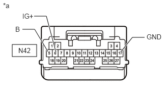
E407119C04
0.25,0.917 0.75,1.167 0.5,0.25 0.979,1.063 0.708,0.604 0.708,0.604 0.458,0.604 true 2.469,1.073 2.708,0.771 2.708,0.771 2.958,0.771 true 1.146,1.083 0.948,0.333 0.948,0.333 0.698,0.333 true 0.375,0.958 0.833,1.156 0.458,0.198 10 false N42 0.313,0.521 0.698,0.688 0.385,0.167 10 false B 0.063,0.031 0.521,0.229 0.458,0.198 10 false *a 0.458,0.25 0.844,0.417 0.385,0.167 10 false IG+ 3,0.677 3.344,0.906 0.344,0.229 10 false GND
*a Front view of wire harness connector
(to Air Conditioning Amplifier Assembly)


Disconnect the air conditioning amplifier assembly connector.


b.

Measure the resistance according to the value(s) in the table below.

Standard Resistance:
Tester Connection Condition Specified Condition
N42-17 (GND) - Body ground Always Below 1 Ω


c.

Measure the voltage according to the value(s) in the table below.

Standard Voltage:
Tester Connection Condition Specified Condition
N42-5 (B) - Body ground Always 11 to 14 V
N42-6 (IG+) - Body ground Ignition switch ON 11 to 14 V
Ignition switch off Below 1 V


Result:
Proceed to
OK
NG


OK

NG

REPAIR OR REPLACE HARNESS OR CONNECTOR

4.CHECK FOR DTC
a.

Result:
Proceed to
OK
NG


OK

5.CHECK HARNESS AND CONNECTOR (AIR CONDITIONING AMPLIFIER ASSEMBLY - BATTERY AND BODY GROUND)

NG

5.CHECK HARNESS AND CONNECTOR (AIR CONDITIONING AMPLIFIER ASSEMBLY - BATTERY AND BODY GROUND)
a.
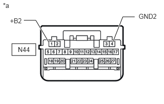
E421586C01
0.25,0.917 0.75,1.167 0.5,0.25 1.021,0.885 0.75,0.427 0.75,0.427 0.5,0.427 true 2.365,0.885 2.573,0.354 2.573,0.354 2.823,0.354 true 0.375,0.958 0.833,1.156 0.458,0.198 10 false N44 0.208,0.354 0.594,0.521 0.385,0.167 10 false +B2 0.063,0.031 0.521,0.229 0.458,0.198 10 false *a 2.906,0.26 3.354,0.479 0.448,0.219 10 false GND2
*a Front view of wire harness connector
(to Air Conditioning Amplifier Assembly)


Disconnect the air conditioning amplifier assembly connector.


b.

Measure the resistance according to the value(s) in the table below.

Standard Resistance:
Tester Connection Condition Specified Condition
N44-4 (GND2) - Body ground Always Below 1 Ω


c.

Measure the voltage according to the value(s) in the table below.

Standard Voltage:
Tester Connection Condition Specified Condition
N44-1 (+B2) - Body ground Always 11 to 14 V


Result:
Proceed to
OK
NG


OK

NG

REPAIR OR REPLACE HARNESS OR CONNECTOR