DOOR / HATCH SLIDE DOOR(for Wagon) DISASSEMBLY
CAUTION / NOTICE / HINT
The necessary procedures (adjustment, calibration, initialization, or registration) that must be performed after parts are removed and installed, or replaced during slide door disassembly/reassembly are shown below.
| Replaced Part or Performed Procedure | Effect/Inoperative Function when Necessary Procedure not Performed | Necessary Procedure | Link |
|---|---|---|---|
| Removal and installation of battery terminal | Parking assist monitor system | Memorize steering angle neutral point | ( 201902,999999,_56,_079315,_0385736,RM100000001GNRA,) 201902,999999,_56,_079315,_0385736,RM100000001GNRA,)
|
| Panoramic view monitor system | (201906,999999,_56,_079315,_0396274,RM100000001IGR3,)
|
- HINT:
-
When the cable is disconnected / reconnected to the battery terminal, systems temporarily stop operating. However, each system has a function that completes learning the first time the system is used.
- ·
Learning completes when vehicle is driven
Effect/Inoperative Function When Necessary Procedures are not Performed Necessary Procedures Link *: w/ Stop and start system
Stop and start system* Drive the vehicle until stop and start control is permitted (approximately 5 to 60 minutes). ( 201902,999999,_51,_078825,_0382334,RM100000001GBQ1,)
Lane control system Drive the vehicle straight ahead at 15 km/h (10 mph) or more for 1 second or more. ( 201902,999999,_58,_078886,_0382740,RM100000001G6XB,)
Pre-collision system
·Learning completes when vehicle is operated normally
Effect/Inoperative Function When Necessary Procedures are not Performed Necessary Procedures Link Power slide door system Fully close the slide door by hand.
- HINT:
-
Initialization is not necessary if the above procedures are performed while the slide door is closed.
( 201902,999999,_59,_078503,_0381017,RM100000001FWXM,)
Air conditioning system After the ignition switch is turned to ON, the servo motor standard position is recognized. -
·Use the same procedure for RHD and LHD vehicles.
·The procedure listed below is for LHD vehicles.
·Use the same procedure for the RH and LH sides.
·Use the same procedure described for the RH side.
PROCEDURE

 1. PRECAUTION (w/ Rear Curtain Shield Airbag)
- CAUTION:
-
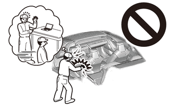
-
Be sure to read Precaution thoroughly before servicing.
- NOTICE:
-
After turning the ignition switch off, waiting time may be required before disconnecting the cable from the negative (-) battery terminal.
2.DISCONNECT CABLE FROM NEGATIVE BATTERY TERMINAL (w/ Rear Curtain Shield Airbag)
- CAUTION:
-
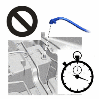
- ·
Wait at least 90 seconds after disconnecting the cable from the negative (-) battery terminal to disable the SRS system.
·If the airbag deploys for any reason, it may cause a serious accident.
67692B
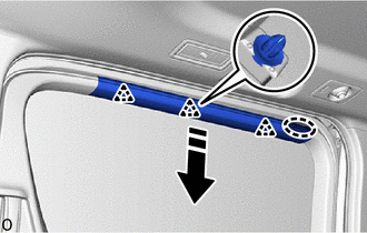
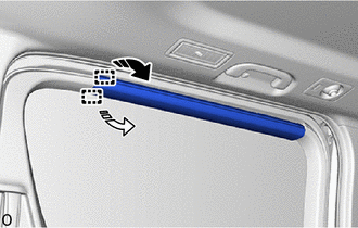
3.REMOVE SLIDE DOOR TRIM UPPER COVER RH
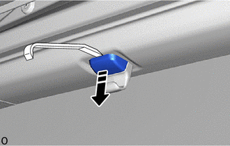

|
Remove in this Direction |
w/ Sunshade
Insert moulding remover A at the position shown in the illustration and lower the pin in the direction indicated by the arrow.
- NOTICE:
-
Do not remove the sunshade hook from the slide door trim upper cover RH.
- HINT:
-
Use the same procedure described for the other side.
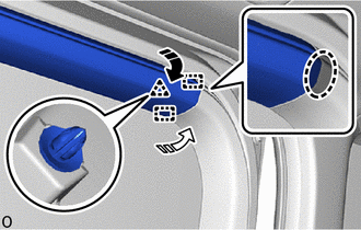

|
Place Hand Here |
|
|
Remove in this Direction (1) |

|
Remove in this Direction (2) |
Place your hand at the position shown in the illustration and detach the guide in the order indicated by the arrow.
Detach the clip.
|
|
Place Hand Here |
|
|
Remove in this Direction |
Place your hand at the position shown in the illustration, and while pulling the slide door trim upper cover RH toward you, detach the clip.
|
|
Remove in this Direction (1) |
|
|
Remove in this Direction (2) |
Detach the guide in the order indicated by the arrow and remove the slide door trim upper cover RH.
- HINT:
-
Remove the sunshade hook together with the slide door trim upper cover RH.
65988A
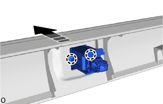
4.REMOVE SUNSHADE HOOK (w/ Sunshade)
|
|
Remove in this Direction |
Detach the claw and remove the sunshade hook in the direction indicated by the arrow shown in the illustration.
- HINT:
-
Use the same procedure described for the other side.
67667A
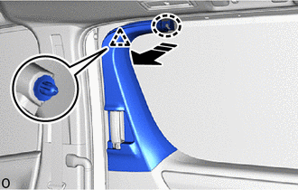
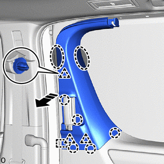
5.REMOVE SLIDE DOOR WINDOW GARNISH RH
|
|
Place Hand Here |
|
|
Remove in this Direction |
Place your hand at the position shown in the illustration, and while pulling the slide door window garnish RH toward you, detach the clip.
|
|
Place Hand Here |
|
|
Remove in this Direction |
Place your hand at the position shown in the illustration, and while pulling the slide door window garnish RH toward you, detach the clip, claw and guide to remove the slide door window garnish RH.
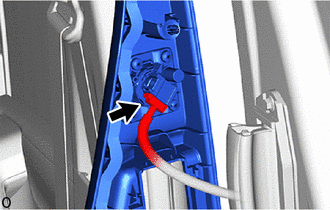
w/ Rear No. 2 Speaker assembly:
Disconnect the connector.
67487A
6.REMOVE REAR DOOR REAR GUIDE BRACKET GARNISH RH
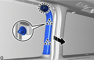
|
|
Place Hand Here |
|
|
Remove in this Direction |
Place your hand at the position shown in the illustration, and while pulling the rear door rear guide bracket garnish RH toward you, detach the clip.
|
|
Place Hand Here |
|
|
Remove in this Direction (1) |
|
|
Remove in this Direction (2) |
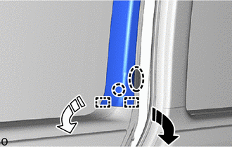
Detach the guide in the order indicated by the arrow, detach the claw and remove the rear door rear guide bracket garnish RH.
81380D
7.REMOVE STEP LIGHT ASSEMBLY
67680B
8.REMOVE SLIDE DOOR TRIM BOARD ASSEMBLY RH
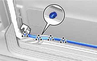
Using a moulding remover B, detach the clip as shown in the illustration.
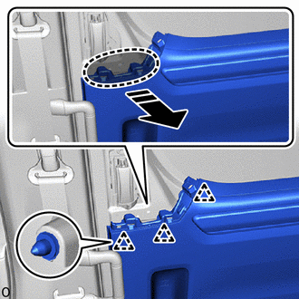
|
|
Place Hand Here |
|
|
Remove in this Direction |
Place your hands at the position shown in the illustration, pull the slide door trim board assembly RH in the direction of the arrow and detach the clip.
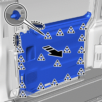
|
|
Place Hand Here |
|
|
Remove in this Direction |
Place your hands at the position shown in the illustration, pull the slide door trim board assembly RH in the direction of the arrow and detach the clip.
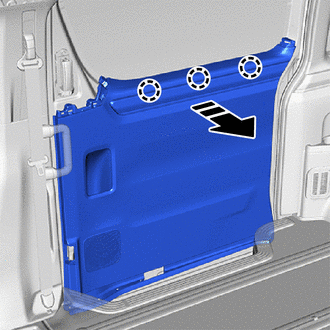
|
|
Remove in this Direction |
Detach the claw and remove the slide door trim board assembly RH in the direction indicated by the arrow shown in the illustration.

Disconnect the connector.
62345B
9.REMOVE NO. 3 SLIDE DOOR WEATHERSTRIP RH
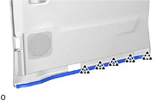
Detach the clip and remove the No. 3 slide door weatherstrip RH.
67851E
10.REMOVE SLIDE DOOR SERVICE HOLE COVER RH
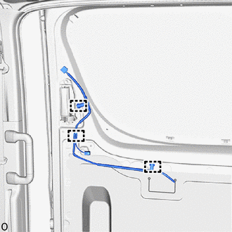
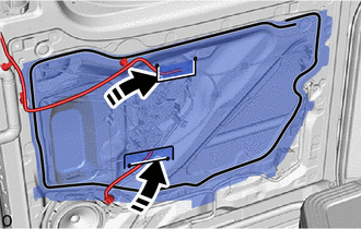
Detach the clamp as shown in the illustration.
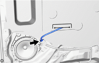
Disconnect the connector.
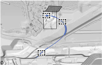
Fold back the slide door service hole cover RH, detach the clamp and disconnect the slide door full open lock sub-assembly cable as shown in the illustration.
Disconnect the cable from the cable clamp.

Detach the clamp and remove the 2 cable clamps.
|
|
Remove in this Direction |
Pull out the rear door wire RH from the slide door service hole cover, and then remove the slide door service hole cover.
- NOTICE:
-
Remove any remaining butyl tape from the slide door panel.
85975A
11.REMOVE SLIDE DOOR CLOSER RELAY (w/o Power Slide Door)
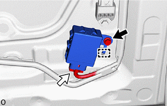

|
Bolt |

|
Connector |
Remove the bolt.
Detach the guide and disconnect the connector to remove the slide door closer relay.
- NOTICE:
- ·
Do not subject the slide door closer relay to strong impacts or force, and do not drop it.
·Do not reuse the slide door closer relay that has been dropped.
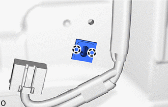
Detach the claw and remove the clip.
69050
12.REMOVE SLIDE DOOR FULL OPEN STOP LOCK ASSEMBLY RH
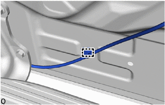
Detach the clamp.
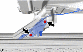
Remove the 2 bolts and slide door full open stop lock assembly RH.
69070
13.REMOVE SLIDE DOOR HANDLE ASSEMBLY RH
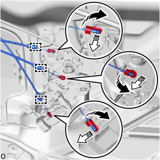
| *a | Locking Cable (Orange) |
| *b | Open Cable (Blue) |
| *c | Close Cable (Purple) |
|
|
Remove in this Direction (1) |
|
|
Remove in this Direction (2) |
Detach the clamp.
Detach the 3 snaps and disconnect the 3 cables from the slide door lock remote control assembly RH as shown in the illustration.
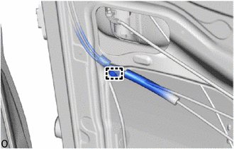
Detach the clamp.
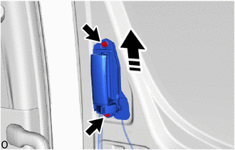
|
|
Remove in this Direction |
Remove the 2 bolts and pull out the slide door handle assembly RH in the direction indicated by the arrow in the illustration to remove the slide door handle assembly RH.
69230
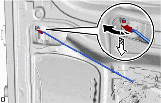
14.REMOVE REAR DOOR OUTSIDE HANDLE ASSEMBLY RH
|
|
Remove in this Direction (1) |
|
|
Remove in this Direction (2) |
Detach the snap in the direction indicated by the arrow (1) as shown in the illustration.
Disconnect the rear door lock remote control link RH in the direction indicated by the arrow (2) as shown in the illustration.
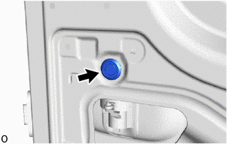
Remove the hole plug.
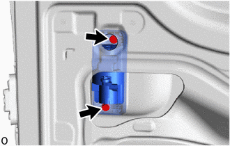
Remove 2 bolts and rear door outside handle assembly RH.
69713A
15.REMOVE REAR DOOR LOCK REMOTE CONTROL LINK RH
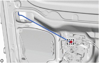
Detach the clamp and remove the rear door lock remote control link RH.
69730A
16.REMOVE REAR DOOR LOCK CONTROL LINK ASSEMBLY RH (w/ Cover)
69370B
17.REMOVE SLIDE DOOR FRONT LOCK ASSEMBLY RH
69330E
18.REMOVE SLIDE DOOR LOCK ASSEMBLY RH (w/o Power Slide Door)
69200
19.REMOVE POWER SLIDE DOOR LOCK ASSEMBLY RH (w/ Power Slide Door)
69630C
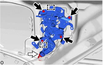
20.REMOVE SLIDE DOOR LOCK REMOTE CONTROL ASSEMBLY RH
|
|
Bolt |
|
|
Connector |
Disconnect the each connector.
Remove the 4 bolts.
Detach the guide and remove the slide door lock remote control assembly RH.
86160B
21.REMOVE REAR SPEAKER ASSEMBLY
89831F
22.REMOVE NO. 3 SIDE AIRBAG SENSOR (w/ Rear Curtain Shield Airbag)
- HINT:
-
Use the same procedure described for the LH side.
84250B
23.REMOVE POWER SLIDE DOOR SENSOR ASSEMBLY RH (w/ Power Slide Door)
67865D
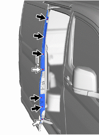
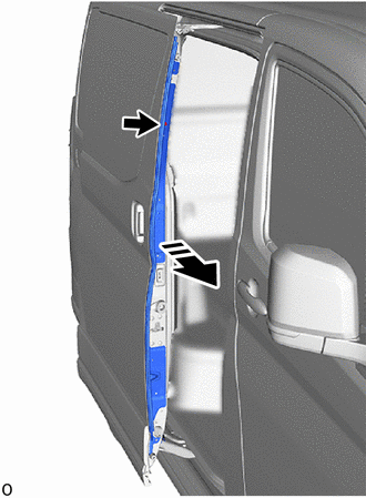
24.REMOVE CENTER PILLAR UPPER END WEATHERSTRIP RH (w/o Power Slide Door)
|
|
Screw |
|
|
Bolt |
Remove the 5 screws and 2 bolts.
|
|
Remove in this Direction |
Detach the double-sided tape to remove the temporary screw and center pillar upper end weatherstrip RH as shown in the illustration.
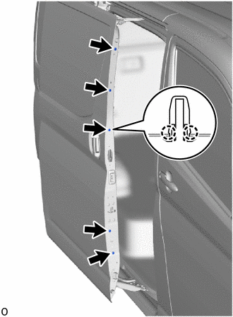
Detach the claw and remove the 5 screw grommets.
69415
25.REMOVE SLIDE DOOR DOWN FEMALE STOPPER
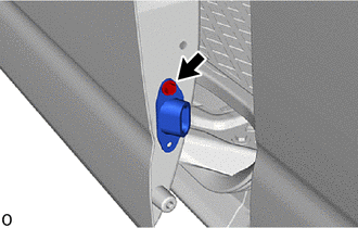
Remove the bolt and slide door down female stopper.
67161B
26.REMOVE SLIDE DOOR UPPER INSIDE PANEL EXTENSION RH (w/ Rear Seat)
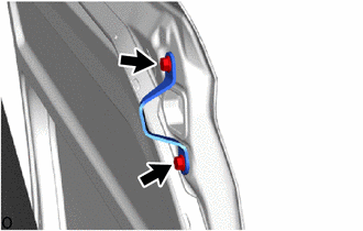
Remove the 2 bolts and slide door upper inside panel extension RH.
67785D
27.REMOVE REAR DOOR UPPER TRIM COVER RH (w/ Rear Seat)
|
|
Remove in this Direction (1) |
|
|
Remove in this Direction (2) |
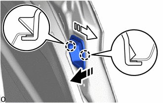
Detach the claw and remove the rear door upper trim cover RH as shown in the illustration.
69425C
28.REMOVE SLIDE DOOR STOP CUSHION (w/o Power Slide Door)
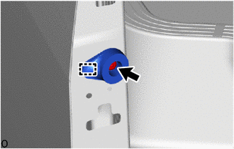
Using a T30 "TORX" socket wrench, remove the "TORX" screw.
Detach the guide and remove the slide door stop cushion.
29.REMOVE CUSHION
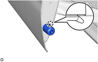
Detach the claw and remove the cushion.
- HINT:
-
Use the same procedure described for the other side.
67837C
30.REMOVE REAR DOOR DUST PROOF SEAL
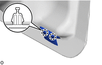
Detach the claw and remove the rear door dust proof seal.
- HINT:
-
Use the same procedure described for the other side.
67917C
31.REMOVE REAR DOOR SCUFF PLATE RH
68394A
32.REMOVE SLIDE DOOR LOWER RAIL PLATE RH (w/o Power Slide Door)
68394A
33.REMOVE SLIDE DOOR LOWER RAIL PLATE RH (w/ Power Slide Door)
51078D
34.REMOVE SIDE STEP BRACKET SUB-ASSEMBLY RH
68073
35.REMOVE SLIDE RAIL END MOULDING SUB-ASSEMBLY RH
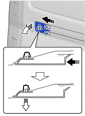
| *a | Clip (part a) |
|
|
Remove in this Direction (1) |
|
|
Remove in this Direction (2) |
Push the slide rail end moulding sub-assembly RH toward the rear of the vehicle, and then while pushing the clip onto the body panel, pull the slide rail end moulding sub-assembly RH toward you, detach the clip (part a) and guide to remove the slide rail end moulding sub-assembly RH.
- NOTICE:
-
If the slide rail end moulding sub-assembly RH cannot be removed even after pulling it toward you, using a screwdriver with its tip wrapped with protective tape, push the clip (part a) toward the rear of the vehicle, detach the clip and remove the slide rail end moulding sub-assembly RH.
67887D
36.REMOVE NO. 2 SLIDE DOOR WEATHERSTRIP RH
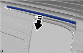
|
|
Remove in this Direction |
Remove the No. 2 slide door weatherstrip RH as shown in the illustration.
- NOTICE:
-
When removing, make sure that non-drying sealer does not adhere to the body and slide door.
68325
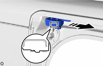
37.REMOVE SLIDE DOOR UPPER RAIL CUSHION RH
|
|
Remove in this Direction |
Detach the guide and remove the slide door upper rail cushion RH as shown in the illustration.
67897M
38.REMOVE NO. 4 SLIDE DOOR WEATHERSTRIP RH

Using a clip remover, detach the clip and remove the No. 4 slide door weatherstrip RH.
67003
39.REMOVE REAR DOOR PANEL SUB-ASSEMBLY RH
|
|
Ground Bolt |
|
|
Connector |
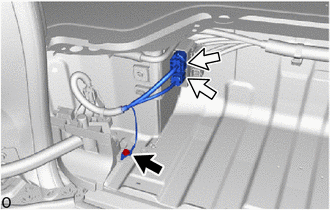
Disconnect the wire harness (w/o Power Slide Door).
Remove the ground bolt and disconnect the ground wire.
Disconnect the 2 connectors.
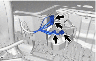
Disconnect the wire harness (w/ Power Slide Door).
Remove the ground bolt and disconnect the ground wire.
Disconnect the 4 connectors.
|
|
Remove in this Direction |
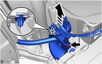
Disconnect the wire harness protector.
Remove the bolt.
Detach the clip and disconnect the wire harness protector as shown in the illustration.
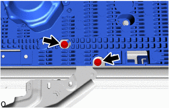
w/ Power Slide Door:
Move the slide door RH so that the 2 bolts are visible as shown in the illustration.
Remove the 2 bolts and disconnect the roller part of the lower slide door roller arm RH from the slide door motor unit RH.
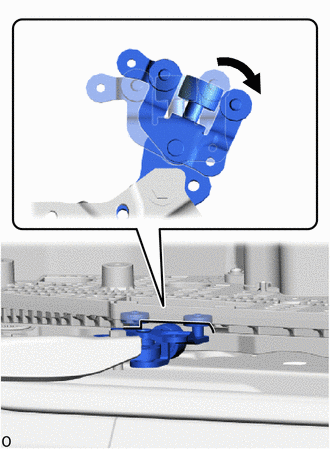
| *a | Cutout |
Rotate the roller part of the slide door lower roller arm sub-assembly RH clockwise to disconnect the slide door lower roller arm sub-assembly RH from the cutout of the rear floor step assembly RH.
- NOTICE:
- ·
Support the lower portion of the slide door RH when disconnecting the slide door lower roller arm sub-assembly RH, as the slide door RH becomes unstable.
·Work with 2 or more persons when disconnecting the slide door RH in order to prevent deformation and damage.
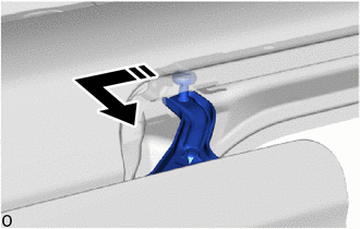
|
|
Remove in this Direction |
Remove the roller part of the slide door upper roller assembly RH from the rear part of the upper slide door rail RH as shown in the illustration.
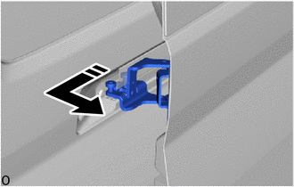
|
|
Remove in this Direction |
Remove the slide door center hinge assembly RH from the rear part of the center slide door rail RH, and then remove the slide door RH as shown in the illustration.
68380D
40.REMOVE SLIDE DOOR CENTER HINGE ASSEMBLY RH
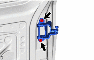
Remove the 2 bolts and slide door center hinge assembly RH.
68301C
41.REMOVE SLIDE DOOR UPPER ROLLER ASSEMBLY RH
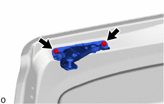
Remove the 2 bolts and slide door upper roller assembly RH.
68335C
42.REMOVE SLIDE DOOR LOWER ROLLER ARM RH
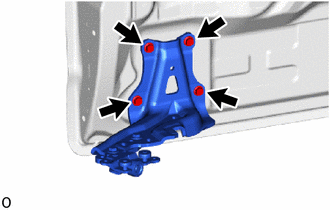
Remove the 4 bolts and slide door lower roller arm RH.
69418L
43.REMOVE SLIDE DOOR OPEN STOP RH
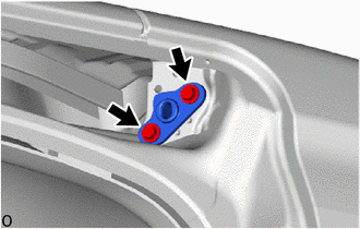
Remove the 2 bolts and slide door open stop RH.
67155C
44.REMOVE REAR DOOR CORNER BRACKET RH (w/ Rear Seat)
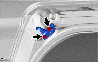
Remove the 2 bolts and rear door corner bracket RH.
69416B
45.REMOVE SLIDE DOOR DOWN MALE STOPPER
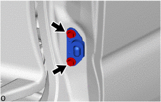
Remove the 2 bolts and slide door down male stopper.
69485D
46.REMOVE SLIDE DOOR OPEN STRIKER RH
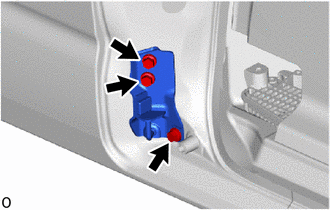
Remove the 3 bolts and slide door open striker RH.
47.REMOVE CUSHION
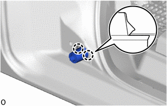
Detach the claw and remove the cushion.