BRAKE SYSTEM (OTHER) VACUUM PUMP(for 7GR-FKS) REMOVAL
CAUTION / NOTICE / HINT
The necessary procedures (adjustment, calibration, initialization, or registration) that must be performed after parts are removed, installed, or replaced during the vacuum pump assembly removal/installation are shown below.
| Replacement Part or Procedure | Necessary Procedures | Effect/Inoperative Function When Necessary Procedures are not Performed | Link |
|---|---|---|---|
| Disconnect cable from negative (-) battery terminal | Memorize steering angle neutral point | Parking assist monitor system | ( 201902,999999,_56,_079315,_0385736,RM100000001GNRA,) 201902,999999,_56,_079315,_0385736,RM100000001GNRA,)
|
| Panoramic view monitor system | (201906,999999,_56,_079315,_0396274,RM100000001IGR3,)
|
- HINT:
-
When the cable is disconnected / reconnected to the battery terminal, systems temporarily stop operating. However, each system has a function that completes learning the first time the system is used.
- ·
Learning completes when vehicle is driven
Effect/Inoperative Function When Necessary Procedures are not Performed Necessary Procedures Link Lane control system Drive the vehicle straight ahead at 15 km/h (10 mph) or more for 1 second or more. ( 201902,999999,_58,_078886,_0382740,RM100000001G6XB,)
Pre-collision system
·Learning completes when vehicle is operated normally
Effect/Inoperative Function When Necessary Procedures are not Performed Necessary Procedures Link Power slide door system Fully close the slide door by hand.
- HINT:
-
Initialization is not necessary if the above procedures are performed while the slide door is closed.
( 201902,999999,_59,_078503,_0381017,RM100000001FWXM,)
Air conditioning system After the ignition switch is turned to ON, the servo motor standard position is recognized. -
PROCEDURE

 1. PRECAUTION
- NOTICE:
-
After turning the ignition switch off, waiting time may be required before disconnecting the cable from the negative (-) battery terminal.
17190
2.REMOVE INTAKE AIR SURGE TANK ASSEMBLY
3.DISCONNECT VACUUM HOSE ASSEMBLY
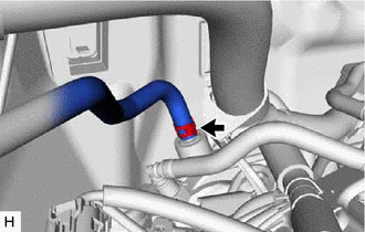
Slide the clip and disconnect the vacuum hose assembly from the vacuum pump assembly.
87249B
4.SEPARATE OUTLET HEATER WATER PIPE B
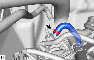
Slide the clip and disconnect the outlet heater water hose B from the outlet heater water pipe B.
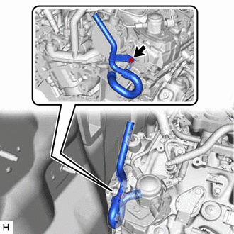
Remove the bolt and separate the outlet heater water pipe B from the engine assembly.
29300
5.REMOVE VACUUM PUMP ASSEMBLY
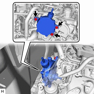
Remove the 3 bolts and vacuum pump assembly from the engine assembly.

| *1 | No. 2 O-ring |
| *2 | No. 3 O-ring |
Remove the No. 2 O-ring and No. 3 O-ring from the vacuum pump assembly.