THEFT DETERRENT / KEYLESS ENTRY THEFT DETERRENT SYSTEM Theft Warning Siren Circuit
DESCRIPTION
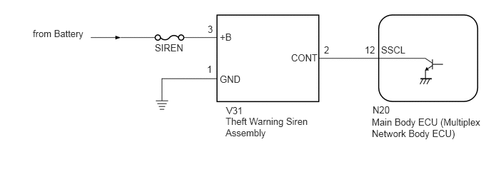
The theft warning siren assembly has an internal battery. If the vehicle battery cable is disconnected or any of the communication lines are open, the theft warning siren assembly detects this and sounds its siren.
Although the theft warning siren assembly usually sounds by receiving a signal from the main body ECU (multiplex network body ECU), the theft warning siren assembly can sound by its internal battery in case the vehicle battery cable is disconnected.
The main body ECU (multiplex network body ECU) sends an arming signal to the theft warning siren assembly while transferring to the armed state, and it also sends a disarming signal to the siren while switching to the disarmed state. Also, the main body ECU (multiplex network body ECU) can cause the theft warning siren assembly to sound by sending an alarm signal during the alarm sounding state.
WIRING DIAGRAM
CAUTION / NOTICE / HINT
- NOTICE:
- ·
w/ Entry and Start System:
If the main body ECU (multiplex network body ECU) is replaced, refer to the Service Bulletin.
·If the theft warning siren assembly is replaced, refer to the Service Bulletin.
·Inspect the fuses for circuits related to this system before performing the following inspection procedure.
PROCEDURE
Connect the GTS to the DLC3.
Turn the ignition switch to ON.
Turn the GTS on.
Enter the following menus: Body Electrical / Main Body / Active Test.
According to the display on the GTS, perform the Active Test.
- Body Electrical > Main Body > Active Test
-
Tester Display Measurement Item Control Range Diagnostic Note Security Horn2 Theft warning siren assembly ON or OFF -
- Body Electrical > Main Body > Active Test
-
Tester Display Security Horn2 - 50004 123 35
- OK:
The theft warning siren assembly sounds and stops correctly when operated through the GTS.
- Result:
Proceed to OK NG
OK
for LHD:
for RHD:
NG
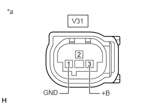
| *a | Front view of wire harness connector
(to Theft Warning Siren Assembly) |
Disconnect the theft warning siren assembly connector.
Measure the voltage according to the value(s) in the table below.
- Standard Voltage:
Tester Connection Condition Specified Condition V31-3 (+B) - Body ground Always 11 to 14 V
Measure the resistance according to the value(s) in the table below.
- Standard Resistance:
Tester Connection Condition Specified Condition V31-1 (GND) - Body ground Always Below 1 Ω
- Result:
Proceed to OK NG
OK
NG
Disconnect the V31 theft warning siren assembly connector.
Disconnect the N20 main body ECU (multiplex network body ECU) connector.
Measure the resistance according to the value(s) in the table below.
- Standard Resistance:
Tester Connection Condition Specified Condition V31-2 (CONT) - N20-12 (SSCL) Always Below 1 Ω V31-2 (CONT) or N20-12 (SSCL) - Other terminals and body ground Always 10 kΩ or higher
- Result:
Proceed to OK NG
OK
NG
Temporarily replace the theft warning siren assembly with a new or normally functioning one.
- HINT:
-
Refer to the Service Bulletin.
Check the operation of the theft warning siren assembly function.
- OK:
Theft warning siren assembly function operates normally.
- Result:
Proceed to OK NG
OK
NG
for LHD:
for RHD: