EXTERIOR PANELS / TRIM BLACK OUT TAPE REMOVAL
CAUTION / NOTICE / HINT
The necessary procedures (adjustment, calibration, initialization, or registration) that must be performed after parts are removed, installed, or replaced during the No. 1 black out tape, No. 2 black out tape, No. 3 black out tape removal/installation are shown below.
| Replaced Part or Performed Procedure | Necessary Procedures | Effect/Inoperative Function When Necessary Procedures are not Performed | Link |
|---|---|---|---|
| Battery terminal is disconnected/reconnected | Memorize steering angle neutral point | Parking assist monitor system | ( 201902,202310,_56,_079315,_0385736,RM100000001GNRA,) 201902,202310,_56,_079315,_0385736,RM100000001GNRA,)
|
| Panoramic view monitor system | (201906,202310,_56,_079315,_0396274,RM100000001IGR3,)
|
||
·
Outer rear view mirror assembly LH (Including removal and installation) ·
Outer rear view mirror assembly RH (Including removal and installation) |
Side television camera view adjustment | Panoramic view monitor system | (201906,202310,_56,_079315,_0396274,RM100000001IGR4,)
|
·
Front television camera assembly, radiator grille assembly or front bumper assembly ·
Television camera assembly ·
Side television camera assembly LH or outer rear view mirror assembly LH ·
Side television camera assembly RH or outer rear view mirror assembly RH |
Television camera view adjustment (Adjustment of all cameras)
|
Panoramic view monitor system | (201906,202310,_56,_079315,_0396274,RM100000001IGR4,)
|
·
Front door glass sub-assembly LH ·
Front door glass sub-assembly RH ·
Front door glass run LH ·
Front door glass run RH |
Initialize power window control system | ·
Auto up and down function ·
Jam protection function ·
Catch protection function ·
Remote control function ·
Key-linked function ·
Wireless transmitter-linked function ·
Key-off operation function |
(201906,999999,_59,_079318,_0384706,RM100000001II57,)
|
- HINT:
-
When the cable is disconnected/reconnected to the auxiliary battery terminal, systems temporarily stop operating. However, each system has a function that completes learning the first time the system is used.
- ·
Learning completes when vehicle is driven
Effect/Inoperative Function When Necessary Procedures are not Performed Necessary Procedures Link *: w/ Stop and start system
Stop and start system* Drive the vehicle until stop and start control is permitted (approximately 5 to 60 minutes). ( 201902,999999,_51,_078825,_0382334,RM100000001GBQ1,)
Lane control system Drive the vehicle straight ahead at 15 km/h (10 mph) or more for 1 second or more. ( 201902,999999,_58,_078886,_0382740,RM100000001G6XB,)
Pre-collision system
·Learning completes when vehicle is operated normally
Effect/Inoperative Function When Necessary Procedures are not Performed Necessary Procedures Link Power slide door system Fully close the slide door by hand.
- HINT:
-
Initialization is not necessary if the above procedures are performed while the slide door is closed.
( 201902,202310,_59,_078503,_0381017,RM100000001FWXM,)
Air conditioning system After the ignition switch is turned to ON, the servo motor standard position is recognized. -
- HINT:
- ·
Use the same procedure for RHD and LHD vehicles.
·The procedure listed below is for LHD vehicles.
·Use the same procedure for the RH and LH sides.
·Use the same procedure described for the LH side.
PROCEDURE

 1.DISCONNECT CABLE FROM NEGATIVE BATTERY TERMINAL
for 1GD-FTV:
Click hereGeneral>MAINTENANCE>1GD-FTV BATTERY>REMOVAL201906,202310,_V1,_078672,_0387106,RM100000001IWLA,
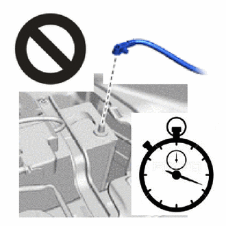
- CAUTION:
-
- ·
Wait at least 90 seconds after disconnecting the cable from the negative (-) battery terminal to disable the SRS system.
·If the airbag deploys for any reason, it may cause a serious accident.
69278B
2.REMOVE FRONT DOOR INSIDE HANDLE BEZEL LH
3.REMOVE MULTIPLEX NETWORK MASTER SWITCH ASSEMBLY WITH FRONT DOOR ARMREST BASE PANEL (for Driver Side)
4.REMOVE POWER WINDOW REGULATOR SWITCH ASSEMBLY WITH FRONT DOOR ARMREST BASE PANEL (for Front Passenger Side)
67602
5.REMOVE FRONT DOOR TRIM BOARD SUB-ASSEMBLY LH
68172A
6.REMOVE FRONT DOOR INNER GLASS WEATHERSTRIP LH
68195B
7.REMOVE FRONT DOOR REAR BELT SEAL LH
68193C
8.REMOVE FRONT DOOR FRONT BELT SEAL LH
75752C
9.REMOVE FRONT DOOR FRONT WINDOW FRAME MOULDING LH
87940
10.REMOVE OUTER REAR VIEW MIRROR ASSEMBLY LH
67832
11.REMOVE FRONT DOOR SERVICE HOLE COVER LH
67836C
12.REMOVE FRONT DOOR NO. 3 SERVICE HOLE COVER LH (w/ Curtain Shield Airbag)
67838F
13.REMOVE FRONT DOOR NO. 4 SERVICE HOLE COVER LH (w/ Curtain Shield Airbag)
68151D
14.DISCONNECT FRONT DOOR GLASS RUN LH
67402F
15.REMOVE FRONT DOOR FRONT LOWER FRAME SUB-ASSEMBLY LH
68102
16.REMOVE FRONT DOOR GLASS SUB-ASSEMBLY LH
68151D
17.REMOVE FRONT DOOR GLASS RUN LH
68126
18.REMOVE FRONT DOOR FIX WINDOW GLASS LH
67862
19.REMOVE FRONT DOOR WEATHERSTRIP LH

|
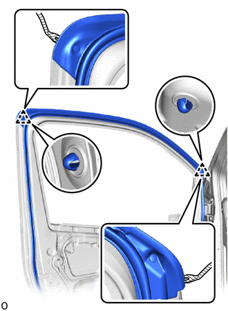
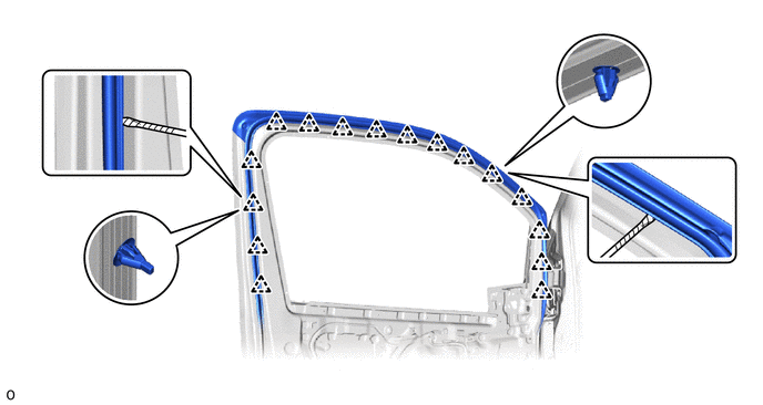
Protective Tape |
Using a clip remover with its tip wrapped with protective tape, detach the clip.
Using a screwdriver with its tip wrapped with protective tape, detach the clip and remove only the part of the front door weatherstrip LH shown in the illustration.
|
|
Protective Tape | - | - |
75926A
20.REMOVE NO. 3 BLACK OUT TAPE LH
- HINT:
-
When removing the No. 3 black out tape LH, if it is difficult to remove, heat the adhesive of the No. 3 black out tape LH and front door panel using a heat light.
- Standard Value:
Part Temperature Front Door Panel 40 to 60°C (104 to 140°F) No. 3 Black Out Tape LH 40 to 60°C (104 to 140°F)
- CAUTION:
-
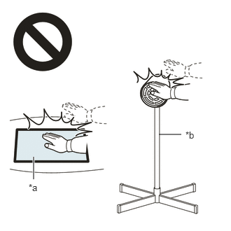 2.365,2 2.698,2 false 0.5,2.333 0.5,2.667 true 0.427,2.708 0.74,2.865 0.313,0.156 10 false *a 2.76,1.927 3.073,2.083 0.313,0.156 10 false *b
*a Heated Part *b Heat Light
- ·
Do not touch the heat light and heated parts.
·Touching the heat light may result in burns.
·Touching heated parts for a long time may result in burns.
- NOTICE:
-
Do not heat the front door panel and No. 3 black out tape LH excessively.
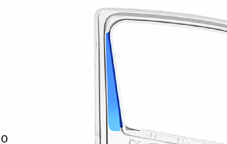
Pull back on one of the ends of the No. 3 black out tape LH to remove it.
- HINT:
-
When pulling on the No. 3 black out tape LH, pull it parallel to the front door panel.
75924B
21.REMOVE NO. 2 BLACK OUT TAPE LH
- HINT:
-
When removing the No. 2 black out tape LH, if it is difficult to remove, heat the adhesive of the No. 2 black out tape LH and front door panel using a heat light.
- Standard Value:
Part Temperature Front Door Panel 40 to 60°C (104 to 140°F) No. 2 Black Out Tape LH 40 to 60°C (104 to 140°F)
- CAUTION:
-
2.365,2 2.698,2 false 0.5,2.333 0.5,2.667 true 0.427,2.708 0.74,2.865 0.313,0.156 10 false *a 2.76,1.927 3.073,2.083 0.313,0.156 10 false *b
*a Heated Part *b Heat Light
- ·
Do not touch the heat light and heated parts.
·Touching the heat light may result in burns.
·Touching heated parts for a long time may result in burns.
- NOTICE:
-
Do not heat the front door panel and No. 2 black out tape LH excessively.
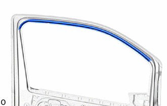
Pull back on one of the ends of the No. 2 black out tape LH to remove it.
- HINT:
-
When pulling on the No. 2 black out tape LH, pull it parallel to the front door panel.
75922M
22.REMOVE NO. 1 BLACK OUT TAPE LH
- HINT:
-
When removing the No. 1 black out tape LH, if it is difficult to remove, heat the adhesive of the No. 1 black out tape LH and front door panel using a heat light.
- Standard Value:
Part Temperature Front Door Panel 40 to 60°C (104 to 140°F) No. 1 Black Out Tape LH 40 to 60°C (104 to 140°F)
- CAUTION:
-
2.365,2 2.698,2 false 0.5,2.333 0.5,2.667 true 0.427,2.708 0.74,2.865 0.313,0.156 10 false *a 2.76,1.927 3.073,2.083 0.313,0.156 10 false *b
*a Heated Part *b Heat Light
- ·
Do not touch the heat light and heated parts.
·Touching the heat light may result in burns.
·Touching heated parts for a long time may result in burns.
- NOTICE:
-
Do not heat the front door panel and No. 1 black out tape LH excessively.
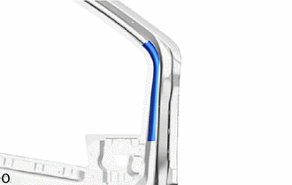
Pull back on one of the ends of the No. 1 black out tape LH to remove it.
- HINT:
-
When pulling on the No. 1 black out tape LH, pull it parallel to the front door panel.