THEFT DETERRENT / KEYLESS ENTRY ENTRY AND START SYSTEM(for Entry Function) All Door Entry Lock/Unlock Functions do not Operate, but Wireless Functions Operate
DESCRIPTION
When the wireless operation can be used to lock and unlock the doors, communication between the door control receiver and certification ECU (smart key ECU assembly) is normal. If the entry lock and unlock functions do not operate, the entry cancel function may be set through the customize function, there may be communication problems between the electrical key transmitter sub-assembly and vehicle, or there may be wave interference.
CAUTION / NOTICE / HINT
- NOTICE:
- ·
When using the GTS with the engine switch off, connect the GTS to the DLC3 and turn a courtesy light switch on and off at intervals of 1.5 seconds or less until communication between the GTS and the vehicle begins. Then select Model Code "KEY REGIST" under manual mode and enter the following menus: Body Electrical / Entry&Start. While using the GTS, periodically turn a courtesy light switch on and off at intervals of 1.5 seconds or less to maintain communication between the GTS and the vehicle.
·The entry and start system (for Entry Function) uses the LIN communication system and CAN communication system. Inspect the communication function by following How to Proceed with Troubleshooting. Troubleshoot the entry and start system (for Entry Function) after confirming that the communication systems are functioning properly.
·Before performing the inspection, check that DTC B1242 (wireless door lock control) is not output.
·Before replacing the certification ECU (smart key ECU assembly) or electrical key transmitter sub-assembly, refer to Service Bulletin.
·After repair, confirm that no DTCs are output.
·Check that there are no electrical key transmitter sub-assemblies in the vehicle.
PROCEDURE
When the door control switch on the multiplex network master switch assembly is operated, check that the doors unlock and lock according to the switch operation.
- OK:
Door locks operate normally.
- Result:
Proceed to OK NG
OK
NG
Connect the GTS to the DLC3.
Turn the engine switch on (IG).
Turn the GTS on.
Enter the following menus: Customize Setting / Entry & Start.
Read the Data List according to the display on the GTS.
- HINT:
-
If the Data List cannot be read, check the value by performing manual operation of the customize function.
- Entry & Start
-
Tester Display Description Default Setting ECU Auto Entry Cancel SW Function that enables or disables the entry and start system. OFF 0:OFF,1:ON Certification ECU (Smart key ECU assembly) - 50006 17
- Result:
Result Proceed to The customize setting is "OFF" A The customize setting is "ON" B
A
B
Move the electrical key transmitter sub-assembly as described below and perform the operation inspection.
- HINT:
- ·
When the electrical key transmitter sub-assembly is brought near the front door outside handle assembly (for Driver Door) or electrical key antenna (outside luggage compartment), the possibility of wave interference decreases, and it can be determined if wave interference is causing the problem symptom.
·If the inspection result is that the problem only occurs in certain locations or at certain times of day, the possibility of wave interference is high. Also, added vehicle components may cause wave interference. If installed, remove them and perform the operation check.
·There may be wave interference if the vehicle is near broadcasting antennas, large video displays, wireless garage door opener systems, wireless security cameras, home security systems, etc. In this case, move the vehicle to a different location and check if there is any improvement.
·If a tool for checking radio waves, such as a signal strength meter, is available, move around the area while observing both the LF band (used by the vehicle antenna to form the detection area) and RF band (used by the electrical key transmitter sub-assembly for transmission) to check for locations where there is wave interference.
·The transmitting wave of the wireless function and entry function are the same, but the wave logic is different. As a result, it is possible that only the wireless function or only the entry function is affected by wave interference.
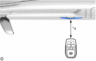
| *a | Approximately 0.3 m (0.984 ft.) |
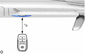
| *a | Approximately 0.3 m (0.984 ft.) |
Bring the electrical key transmitter sub-assembly approximately 0.3 m (0.984 ft.) from the front door outside handle assembly (for Driver Door) and perform a driver door entry lock and unlock operation check.
- HINT:
-
Communication may not be possible if the electrical key transmitter sub-assembly is within 0.2 m (0.656 ft.) of the door handle.
| *a | Approximately 0.3 m (0.984 ft.) |
| *a | Approximately 0.3 m (0.984 ft.) |
Bring the electrical key transmitter sub-assembly approximately 0.3 m (0.984 ft.) from the front door outside handle assembly (for Front Passenger Door) and perform a front passenger door entry lock and unlock operation check.
- HINT:
-
Communication may not be possible if the electrical key transmitter sub-assembly is within 0.2 m (0.656 ft.) of the door handle.
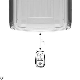
| *a | Approximately 0.3 m (0.984 ft.) |
Bring the electrical key transmitter sub-assembly approximately 0.3 m (0.984 ft.) from the electrical key antenna (outside luggage compartment) and perform an entry back door unlock function check.
- HINT:
-
Communication may not be possible if the electrical key transmitter sub-assembly is within 0.2 m (0.656 ft.) of the rear bumper.
- Result:
Result Proceed to All operation checks fail A All operation checks are normal B Some operation checks are normal C
A
B
C
Enter the following menus: Body Electrical / Entry&Start / Utility / Communication Check(Key Diag Mode).
Check the following antennas in key diagnostic mode.
- Body Electrical > Entry&Start > Utility
-
Tester Display Communication Check(Key Diag Mode) - 50005 125 143
Select either channel 1 or channel 2 and perform key diagnostic mode inspection for each channel.
| *a | 0.7 to 1 m (2.30 to 3.28 ft.) |
| *a | 0.7 to 1 m (2.30 to 3.28 ft.) |
Check the electrical key antenna (for Driver Door):
When the electrical key transmitter sub-assembly is brought within 0.7 to 1 m (2.30 to 3.28 ft.) of the front door outside handle assembly (for Driver Door), check that the buzzer sounds.
- HINT:
- ·
Select either channel 1 or channel 2 and perform the key diagnostic mode inspection for each channel.
·If the buzzer sounds with [CH1] displayed but not with [CH2], the electrical key transmitter sub-assembly cannot be detected by channel 2 due to a malfunction, such as wave interference.
| *a | 0.7 to 1 m (2.30 to 3.28 ft.) |
| *a | 0.7 to 1 m (2.30 to 3.28 ft.) |
Check the electrical key antenna (for Front Passenger Door):
When the electrical key transmitter sub-assembly is brought within 0.7 to 1 m (2.30 to 3.28 ft.) of the front door outside handle assembly (for Front Passenger Door), check that the buzzer sounds.
- HINT:
- ·
Select either channel 1 or channel 2 and perform the key diagnostic mode inspection for each channel.
·If the buzzer sounds with [CH1] displayed but not with [CH2], the electrical key transmitter sub-assembly cannot be detected by channel 2 due to a malfunction, such as wave interference.
| *a | 0.7 to 1 m (2.30 to 3.28 ft.) |
Check the electrical key antenna (outside luggage compartment):
When the electrical key transmitter sub-assembly is brought within 0.7 to 1 m (2.30 to 3.28 ft.) of the electrical key antenna (outside luggage compartment), check that the buzzer sounds.
- HINT:
- ·
Select either channel 1 or channel 2 and perform the key diagnostic mode inspection for each channel.
·If the buzzer sounds with [CH1] displayed but not with [CH2], the electrical key transmitter sub-assembly cannot be detected by channel 2 due to a malfunction, such as wave interference.
- OK:
Buzzer sounds.
- Result:
Result Proceed to All diagnostic mode inspections fail A Some diagnostic mode inspections fail (door) B Some diagnostic mode inspections fail (outside luggage compartment) C All diagnostic mode inspections are normal D
A
B
C
D
Check if there is another electrical key transmitter sub-assembly available that is already registered to the vehicle.
- Result:
Result Proceed to Another registered electrical key transmitter sub-assembly is not available A Another registered electrical key transmitter sub-assembly is available B
A
B
Register a new electrical key transmitter sub-assembly.
- HINT:
-
Refer to Service Bulletin.
- Result:
Proceed to NEXT
NEXT
Using another registered electrical key transmitter sub-assembly, check that the entry function operates normally.
- Result:
Result Proceed to Entry function operates normally A Entry function does not operate normally B
A
B