LIGHTING (EXT) LIGHTING SYSTEM(w/ Headlight ECU) Clearance Light/Daytime Running Light Circuit
DESCRIPTION
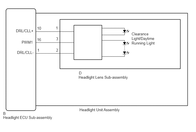
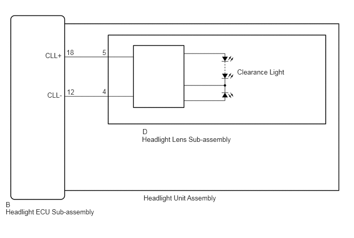
When the main body ECU (multiplex network body ECU) receives the light control switch position signal, it sends an illumination request signal to the headlight ECU sub-assembly LH/RH and illuminates the clearance lights.
When the operation conditions of the daytime running lights are met, the main body ECU (multiplex network body ECU) sends an illumination request signal to the headlight ECU sub-assembly LH/RH and illuminates the daytime running lights.
WIRING DIAGRAM
w/ Daytime Running Light
w/o Daytime Running Light
CAUTION / NOTICE / HINT
- NOTICE:
- ·
If the headlight ECU sub-assembly LH has been replaced, it is necessary to synchronize the vehicle information and initialize the headlight ECU sub-assembly LH.
·When replacing the headlight ECU sub-assembly LH, always replace it with a new one. If a headlight ECU sub-assembly LH which was installed to another vehicle is used, the information stored in it will not match the information from the vehicle and a DTC may be stored.
PROCEDURE
Choose the model to be inspected.
- Result:
Result Proceed to w/ Daytime Running Light A w/o Daytime Running Light B
A
B
Check the illumination of each clearance lights and daytime running lights.
- Result:
Result Proceed to LH side clearance lights and daytime running lights do not illuminate A RH side clearance lights and daytime running lights do not illuminate B
A
B
Connect the GTS to the DLC3.
Turn the engine switch on (IG).
Turn the GTS on.
Enter the following menus: Body Electrical / HL AutoLeveling / Active Test.
Perform the Active Test according to the display on the GTS.
- Body Electrical > HL AutoLeveling > Active Test
-
Tester Display Measurement Item Control Range Diagnostic Note Clearance Light Clearance lights OFF or ON - Daytime Running Light Daytime running lights OFF or ON -
- Body Electrical > HL AutoLeveling > Active Test
-
Tester Display Clearance Light - 50004 361 17
- Body Electrical > HL AutoLeveling > Active Test
-
Tester Display Daytime Running Light - 50004 361 20
- OK:
Clearance lights and daytime running lights illuminate.
- Result:
Proceed to OK NG
OK
NG
Interchange the headlight unit assembly LH with RH and connect the connectors.
- Result:
Proceed to NEXT
NEXT
Check the operation of the clearance lights and daytime running lights.
- Result:
Result Proceed to LH side clearance lights and daytime running lights do not illuminate. A RH side clearance lights and daytime running lights do not illuminate. B
A
B
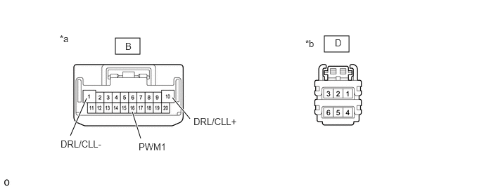
| *a | Component without harness connected
(to Headlight ECU Sub-assembly LH) |
*b | Component without harness connected
(to Headlight Lens Sub-assembly LH) |
Remove the headlight assembly LH.
Remove the headlight lens sub-assembly LH.
Measure the resistance according to the value(s) in the table below.
- Standard Resistance:
Tester Connection Wiring Color Condition Specified Condition B-10 (DRL/CLL+) - D-1 R Always Below 1 Ω B-16 (PWM1) - D-3 O Always Below 1 Ω B-1 (DRL/CLL-) - D-2 B Always Below 1 Ω
- Result:
Proceed to OK NG
OK
NG
Connect the GTS to the DLC3.
Turn the engine switch on (IG).
Turn the GTS on.
Enter the following menus: Body Electrical / HL AutoLeveling (Sub) / Active Test.
Perform the Active Test according to the display on the GTS.
- Body Electrical > HL AutoLeveling (Sub) > Active Test
-
Tester Display Measurement Item Control Range Diagnostic Note Clearance Light Clearance lights OFF or ON - Daytime Running Light Daytime running lights OFF or ON -
- Body Electrical > HL AutoLeveling (Sub) > Active Test
-
Tester Display Clearance Light - 50004 414 2
- Body Electrical > HL AutoLeveling (Sub) > Active Test
-
Tester Display Daytime Running Light - 50004 414 5
- OK:
Clearance lights and daytime running lights illuminate.
- Result:
Proceed to OK NG
OK
NG
Interchange the headlight unit assembly RH with LH and connect the connectors.
- Result:
Proceed to NEXT
NEXT
Check the operation of the clearance lights and daytime running lights.
- Result:
Result Proceed to RH side clearance lights and daytime running lights do not illuminate. A LH side clearance lights and daytime running lights do not illuminate. B
A
B
| *a | Component without harness connected
(to Headlight ECU Sub-assembly RH) |
*b | Component without harness connected
(to Headlight Lens Sub-assembly RH) |
Remove the headlight assembly RH.
Remove the headlight lens sub-assembly RH.
Measure the resistance according to the value(s) in the table below.
- Standard Resistance:
Tester Connection Wiring Color Condition Specified Condition B-10 (DRL/CLL+) - D-1 R Always Below 1 Ω B-16 (PWM1) - D-3 O Always Below 1 Ω B-1 (DRL/CLL-) - D-2 B Always Below 1 Ω
- Result:
Proceed to OK NG
OK
NG
Check the illumination of each clearance lights.
- Result:
Result Proceed to LH side clearance lights do not illuminate A RH side clearance lights do not illuminate B
A
B
Connect the GTS to the DLC3.
Turn the engine switch on (IG).
Turn the GTS on.
Enter the following menus: Body Electrical / HL AutoLeveling / Active Test.
Perform the Active Test according to the display on the GTS.
- Body Electrical > HL AutoLeveling > Active Test
-
Tester Display Measurement Item Control Range Diagnostic Note Clearance Light Clearance lights OFF or ON -
- Body Electrical > HL AutoLeveling > Active Test
-
Tester Display Clearance Light - 50004 361 17
- OK:
Clearance lights illuminate.
- Result:
Proceed to OK NG
OK
NG
Interchange the headlight unit assembly LH with RH and connect the connectors.
- Result:
Proceed to NEXT
NEXT
Check the operation of the clearance lights.
- Result:
Result Proceed to LH side clearance lights do not illuminate. A RH side clearance lights do not illuminate. B
A
B

| *a | Component without harness connected
(to Headlight ECU Sub-assembly LH) |
*b | Component without harness connected
(to Headlight Lens Sub-assembly LH) |
Remove the headlight assembly LH.
Remove the headlight lens sub-assembly LH.
Measure the resistance according to the value(s) in the table below.
- Standard Resistance:
Tester Connection Wiring Color Condition Specified Condition B-18 (CLL+) - D-5 B-R Always Below 1 Ω B-12 (CLL-) - D-4 W-R Always Below 1 Ω
- Result:
Proceed to OK NG
OK
NG
Connect the GTS to the DLC3.
Turn the engine switch on (IG).
Turn the GTS on.
Enter the following menus: Body Electrical / HL AutoLeveling (Sub) / Active Test.
Perform the Active Test according to the display on the GTS.
- Body Electrical > HL AutoLeveling (Sub) > Active Test
-
Tester Display Measurement Item Control Range Diagnostic Note Clearance Light Clearance lights OFF or ON -
- Body Electrical > HL AutoLeveling (Sub) > Active Test
-
Tester Display Clearance Light - 50004 414 2
- OK:
Clearance lights illuminate.
- Result:
Proceed to OK NG
OK
NG
Interchange the headlight unit assembly RH with LH and connect the connectors.
- Result:
Proceed to NEXT
NEXT
Check the operation of the clearance lights.
- Result:
Result Proceed to RH side clearance lights do not illuminate. A LH side clearance lights do not illuminate. B
A
B
| *a | Component without harness connected
(to Headlight ECU Sub-assembly RH) |
*b | Component without harness connected
(to Headlight Lens Sub-assembly RH) |
Remove the headlight assembly RH.
Remove the headlight lens sub-assembly RH.
Measure the resistance according to the value(s) in the table below.
- Standard Resistance:
Tester Connection Wiring Color Condition Specified Condition B-18 (CLL+) - D-5 B-R Always Below 1 Ω B-12 (CLL-) - D-4 W-R Always Below 1 Ω
- Result:
Proceed to OK NG
OK
NG