HEATING / AIR CONDITIONING AIR CONDITIONING SYSTEM(for Automatic Air Conditioning System) B1497 Communication Malfunction (Bus Ic)
DESCRIPTION
The air conditioning harness assembly connects the air conditioning amplifier assembly and the servo motors. The air conditioning amplifier assembly supplies power and sends operation instructions to each servo motor through the air conditioning harness assembly. Each servo motor sends damper position information to the air conditioning amplifier assembly.
| DTC No. | Detection Item | DTC Detection Condition | Trouble Area | Memory |
|---|---|---|---|---|
| B1497 | Communication Malfunction (Bus Ic) | ·
Diagnosis condition: None ·
Malfunction status: Error or open in communication line between air conditioning amplifier assembly and servo motor |
for Front:
·
Air conditioning harness assembly ·
No. 1 air conditioning radiator damper servo sub-assembly ·
No. 1 blower damper servo sub-assembly ·
Air conditioning amplifier assembly for Rear (w/ Integration Control Panel (for Rear Automatic Air Conditioning))
·
No. 2 air conditioning harness assembly ·
No. 1 rear cooling unit damper servo sub-assembly ·
No. 2 rear cooling unit damper servo sub-assembly ·
Air conditioning amplifier assembly |
Memorized |
WIRING DIAGRAM
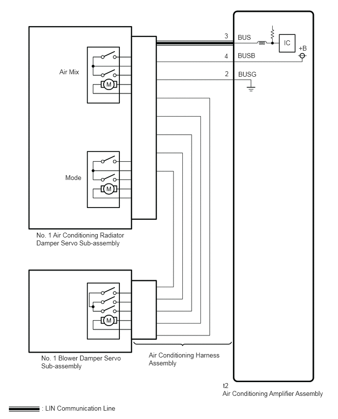
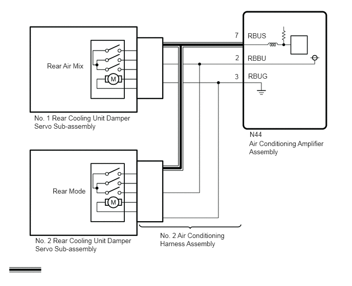
PROCEDURE
Connect the GTS to the DLC3.
Turn the ignition switch to ON.
Turn the GTS on.
Enter the following menus: Body Electrical / Air Conditioner / Active Test.
Check the operation by referring to the table below.
- Body Electrical > Air Conditioner > Active Test
-
Tester Display Measurement Item Control Range Diagnostic Note Air Mix Servo Targ Pulse(D) No. 1 air conditioning radiator damper servo sub-assembly (air mix) pulse Min.: 128
Max.: 383Operates between 165 to 257 pulses Air Outlet Servo Pulse (D) No. 1 air conditioning radiator damper servo sub-assembly (mode) pulse Min.: 128
Max.: 383Operates between 256 to 348 pulses Air Inlet Damper Targ Pulse No. 1 blower damper servo sub-assembly pulse Min.: 128
Max.: 383for 1 Layer Type:Operates between 235 to 258 pulses
for 2 Layer Type:Operates between 220 to 256 pulses
Rear Air Mix Servo Targ Pulse No. 1 rear cooling unit damper servo motor sub-assembly (rear air mix) target pulse Min.: 128
Max.: 383Operates between 254 and 299 pulses
(w/ Integration Control and Panel (for Rear Automatic Conditioning))A/O Servo Pulse(Rr D) No. 2 rear cooling unit damper servo motor sub-assembly (rear mode) target pulse Min.: 128
Max.: 383Operates between 200 and 276 pulses
(w/ Integration Control and Panel (for Rear Automatic Air Conditioning))
- Body Electrical > Air Conditioner > Active Test
-
Tester Display Air Mix Servo Targ Pulse(D) - 50004 121 24
- Body Electrical > Air Conditioner > Active Test
-
Tester Display Air Outlet Servo Pulse (D) - 50004 121 26
- Body Electrical > Air Conditioner > Active Test
-
Tester Display Air Inlet Damper Targ Pulse - 50004 121 27
- Body Electrical > Air Conditioner > Active Test
-
Tester Display Rear Air Mix Servo Targ Pulse - 50004 121 36
- Body Electrical > Air Conditioner > Active Test
-
Tester Display A/O Servo Pulse(Rr D) - 50004 121 56
- OK:
Damper servo motor is operated.
Check the operation by referring to the table below.
- Result:
Result Proceed to All damper servo motors are not operated (for Front) A All damper servo motors are not operated (for Rear) (w/ Integration Control and Panel (for Rear Automatic Air Conditioning)) B Any damper servo motor is not operated (for Front) C Any damper servo motor is not operated (for Rear) (w/ Integration Control and Panel (for Rear Automatic Air Conditioning)) D All damper servo motors are operated E
A
B
C
D
E
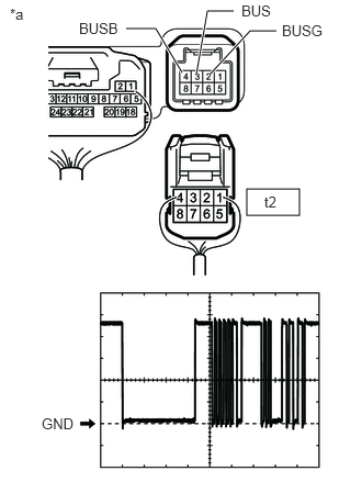
| *a | Component without harness connected
(Air Conditioning Amplifier Assembly) |
Disconnect the air conditioning amplifier assembly connector.
Measure the resistance according to the value(s) in the table below.
- Standard Resistance:
Tester Connection Condition Specified Condition 2 (BUSG) - Body ground Always Below 1 Ω
Measure the voltage according to the value(s) in the table below.
- Standard Voltage:
Tester Connection Condition Specified Condition 2 (BUSG) - 4 (BUSB) Always 11 to 14 V
Using an oscilloscope, check the waveform.
| Item | Content |
|---|---|
| Tester Connection | 2 (BUSG) - 3 (BUS) |
| Tool Setting | 2 V/DIV., 20 μs/DIV. |
| Condition | Ignition switch ON |
- OK:
The waveform displays properly.
- Result:
Proceed to OK NG
OK
NG
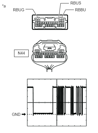
| *a | Component without harness connected
(Air Conditioning Amplifier Assembly) |
Disconnect the air conditioning amplifier assembly connector.
Measure the resistance according to the value(s) in the table below.
- Standard Resistance:
Tester Connection Condition Specified Condition 3 (RBUG) - Body ground Always Below 1 Ω
Measure the voltage according to the value(s) in the table below.
- Standard Voltage:
Tester Connection Condition Specified Condition 2 (RBBU) - 3 (RBUG) Always 11 to 14 V
Using an oscilloscope, check the waveform.
| Item | Content |
|---|---|
| Tester Connection | 3 (RBUG) - 7 (RBUS) |
| Tool Setting | 2 V/DIV., 20 μs/DIV. |
| Condition | Ignition switch ON |
- OK:
The waveform displays properly.
- Result:
Proceed to OK NG
OK
NG