HEATING / AIR CONDITIONING AIR CONDITIONING SYSTEM(for Automatic Air Conditioning System) Clock Communication Error
WIRING DIAGRAM
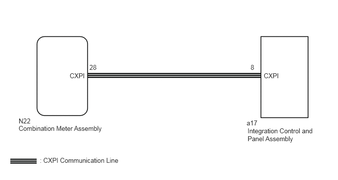
CAUTION / NOTICE / HINT
- NOTICE:
-
When replacing the combination meter assembly, always replace it with a new one. If a combination meter assembly which was installed to another vehicle is used, the information stored in it will not match the information from the vehicle and a DTC may be stored.
PROCEDURE
Check if the clock function in the combination meter assembly operates normally.
- OK:
The clock function in the combination meter assembly operates normally.
- Result:
Proceed to OK NG
OK
NG
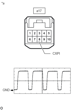
| *a | Front view of wire harness connector
(to Integration Control and Panel Assembly) |
Check the output waveform.
Disconnect the integration control and panel assembly connector.
Connect an oscilloscope to terminal 8 (CXPI) and body ground.
Turn the ignition switch to ON.
Check the signal waveform according to the condition(s) in the table below.
| Item | Condition |
|---|---|
| Terminal No. | a17-8 (CXPI) - Body ground |
| Tool Setting | 2 V/DIV., 20 μs./DIV. |
| Vehicle Condition | Ignition switch ON |
- OK:
The waveform is similar to that shown in the illustration.
- HINT:
-
The waveform varies depending on the CXPI communication signal.
- Result:
Proceed to OK NG
OK
NG
Disconnect the N22 combination meter assembly connector.
Disconnect the a17 integration control and panel assembly connector.
Measure the resistance according to the value(s) in the table below.
- Standard Resistance:
Tester Connection Condition Specified Condition N22-28 (CXPI) - a17-8 (CXPI) Always Below 1 Ω N22-28 (CXPI) - Other terminals and body ground Always 10 kΩ or higher
- Result:
Proceed to OK NG
OK
NG