7GR-FKS ENGINE CONTROL SFI SYSTEM P21CF13 Cylinder 1 Injector "B" Circuit Open P21D013 Cylinder 2 Injector "B" Circuit Open P21D113 Cylinder 3 Injector "B" Circuit Open P21D213 Cylinder 4 Injector "B" Circuit Open P21D313 Cylinder 5 Injector "B" Circuit Open P21D413 Cylinder 6 Injector "B" Circuit Open
DESCRIPTION
The D-4S system has two injection systems. One is an in-cylinder direct injection system that directly injects pressurized fuel into the combustion chamber. The other is an intake port injection system. The ECM determines the percentage of direct injection and port injection necessary in accordance with the engine speed and load.
| DTC No. | Detection Item | DTC Detection Condition | Trouble Area | MIL | Memory | Note |
|---|---|---|---|---|---|---|
| P21CF13 | Cylinder 1 Injector "B" Circuit Open | Current is not applied to the injector 10 times or more with the engine running (1 trip detection logic). | ·
Open or short in fuel injector assembly (for port injection) circuit ·
Fuel injector assembly (for port injection) ·
ECM |
Comes on | DTC stored | SAE Code: P21CF |
| P21D013 | Cylinder 2 Injector "B" Circuit Open | Current is not applied to the injector 10 times or more with the engine running (1 trip detection logic). | ·
Open or short in fuel injector assembly (for port injection) circuit ·
Fuel injector assembly (for port injection) ·
ECM |
Comes on | DTC stored | SAE Code: P21D0 |
| P21D113 | Cylinder 3 Injector "B" Circuit Open | Current is not applied to the injector 10 times or more with the engine running (1 trip detection logic). | ·
Open or short in fuel injector assembly (for port injection) circuit ·
Fuel injector assembly (for port injection) ·
ECM |
Comes on | DTC stored | SAE Code: P21D1 |
| P21D213 | Cylinder 4 Injector "B" Circuit Open | Current is not applied to the injector 10 times or more with the engine running (1 trip detection logic). | ·
Open or short in fuel injector assembly (for port injection) circuit ·
Fuel injector assembly (for port injection) ·
ECM |
Comes on | DTC stored | SAE Code: P21D2 |
| P21D313 | Cylinder 5 Injector "B" Circuit Open | Current is not applied to the injector 10 times or more with the engine running (1 trip detection logic). | ·
Open or short in fuel injector assembly (for port injection) circuit ·
Fuel injector assembly (for port injection) ·
ECM |
Comes on | DTC stored | SAE Code: P21D3 |
| P21D413 | Cylinder 6 Injector "B" Circuit Open | Current is not applied to the injector 10 times or more with the engine running (1 trip detection logic). | ·
Open or short in fuel injector assembly (for port injection) circuit ·
Fuel injector assembly (for port injection) ·
ECM |
Comes on | DTC stored | SAE Code: P21D4 |
MONITOR DESCRIPTION
The ECM monitors the injection control of the fuel injector assemblies (for port injection). If a malfunction is detected in a fuel injector assembly (for port injection) circuit, the ECM cancels the injection control for the corresponding cylinder, illuminates the MIL and stores a DTC.
MONITOR STRATEGY
| Required Sensors/Components | Port injector (cylinder 1 to 6) |
| Frequency of Operation | Continuous |
CONFIRMATION DRIVING PATTERN
Connect the GTS to the DLC3.
Turn the ignition switch to ON.
Turn the GTS on.
Clear the DTCs (even if no DTCs are stored, perform the clear DTC procedure).
Turn the ignition switch off and wait for at least 30 seconds.
Start the engine [A].
Idle the engine for 3 minutes or more [B].
Turn the GTS on.
Enter the following menus: Powertrain / Engine / Trouble Codes [C].
Read the DTCs [B].
- HINT:
- ·
If a pending DTC is output, the system is malfunctioning.
·If a pending DTC is not output, perform the following procedure.
Enter the following menus: Powertrain / Engine / Utility / All Readiness.
Input the DTC: P21CF13, P21D013, P21D113, P21D213, P212313 or P212413.
Check the DTC judgment result.
| GTS Display | Description |
|---|---|
| NORMAL | ·
DTC judgment completed ·
System normal |
| ABNORMAL | ·
DTC judgment completed ·
System abnormal |
| INCOMPLETE | ·
DTC judgment not completed ·
Perform driving pattern after confirming DTC enabling conditions |
- HINT:
- ·
If the judgment result is NORMAL, the system is normal.
·If the judgment result is ABNORMAL, the system has a malfunction.
·If the judgment result is INCOMPLETE, perform steps [B] through [C] again.
WIRING DIAGRAM
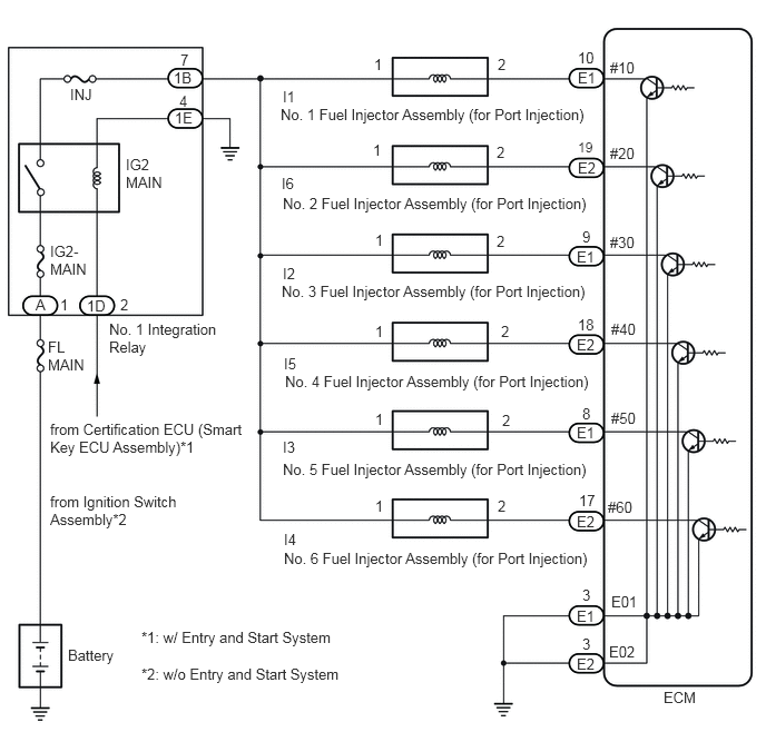
CAUTION / NOTICE / HINT
- NOTICE:
-
Inspect the fuses for circuits related to this system before performing the following procedure.
- HINT:
-
Read Freeze Frame Data using the GTS. The ECM records vehicle and driving condition information as Freeze Frame Data the moment a DTC is stored. When troubleshooting, Freeze Frame Data can help determine if the vehicle was moving or stationary, if the engine was warmed up or not, if the air fuel ratio was lean or rich, and other data from the time the malfunction occurred.
PROCEDURE
Connect the GTS to the DLC3.
Turn the ignition switch to ON.
Turn the GTS on.
Enter the following menus: Powertrain / Engine / Trouble Codes.
Read the DTCs.
- Powertrain > Engine > Trouble Codes
- 50001 372
- Result:
Result Proceed to P21CF13, P21D013, P21D113, P21D213, P21D313 or P21D413 is output A P21CF13, P21D013, P21D113, P22D213, P21D313 and P21D413 are output B
A
B
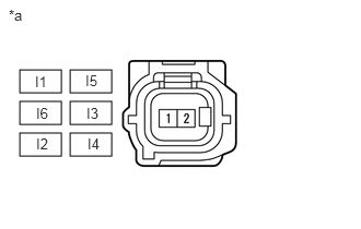
| *a | Front view of wire harness connector
(to Fuel Injector Assembly (for Port Injection)) |
Disconnect the fuel injector assembly (for port injection) connector.
Turn the ignition switch to ON.
Measure the voltage according to the value(s) in the table below
- Standard Voltage:
Tester Connection Condition Specified Condition I1-1 - Body ground Ignition switch ON 11 to 14 V I6-1 - Body ground Ignition switch ON 11 to 14 V I2-1 - Body ground Ignition switch ON 11 to 14 V I5-1 - Body ground Ignition switch ON 11 to 14 V I3-1 - Body ground Ignition switch ON 11 to 14 V I4-1 - Body ground Ignition switch ON 11 to 14 V
- Result:
Proceed to OK NG
OK
NG
Disconnect the ECM connector.
Disconnect the fuel injector assembly (for port injection) connector.
Measure the resistance according to the value(s) in the table below.
- Standard Resistance:
Tester Connection Condition Specified Condition I1-2 - E1-10 (#10) Always Below 1 Ω I6-2 - E2-19 (#20) Always Below 1 Ω I2-2 - E1-9 (#30) Always Below 1 Ω I5-2 - E2-18 (#40) Always Below 1 Ω I3-2 - E1-8 (#50) Always Below 1 Ω I4-2 - E2-17 (#60) Always Below 1 Ω I1-2 or E1-10 (#10) - Body ground and other terminals Always 10 kΩ or higher I6-2 or E2-19 (#20) - Body ground and other terminals Always 10 kΩ or higher I2-2 or E1-9 (#30) - Body ground and other terminals Always 10 kΩ or higher I5-2 or E2-18 (#40) - Body ground and other terminals Always 10 kΩ or higher I3-2 or E1-8 (#50) - Body ground and other terminals Always 10 kΩ or higher I4-2 or E2-17 (#60) - Body ground and other terminals Always 10 kΩ or higher
- Result:
Proceed to OK NG
OK
NG
Inspect the fuel injector assembly (for port injection).
- HINT:
-
Perform "Inspection After Repair" after replacing the fuel injector assembly (for port injection).
- Result:
Proceed to OK NG
OK
NG