HEATING / AIR CONDITIONING AIR CONDITIONING SYSTEM(for Heater System) PTC Heater Circuit
DESCRIPTION
The air conditioning amplifier assembly sends operation signals to the PTC heater relays when quick heater assembly operation conditions are met. Based on the signals from the air conditioning amplifier assembly, the PTC heater relays turn on, and power is supplied to the quick heater assembly installed in the air conditioning radiator assembly.
| Control ECU | Condition |
|---|---|
| Air Conditioning Amplifier Assembly | Start the engine |
| ECO driver mode: Off | |
| Blower switch: On | |
| Temperature settings: MAX HOT | |
| Light control switch: Off | |
·
Engine coolant temperature 65°C (149°F), or lower (3 PTC heater relays operating) ·
Engine coolant temperature 70°C (158°F), or lower (2 PTC heater relays operating) ·
Engine coolant temperature 75°C (167°F), or lower (A PTC heater relay operating) |
|
·
Ambient temperature -10°C (14°F) or lower (3 PTC heater relays operating) ·
Ambient temperature 0°C (32°F) or lower (2 PTC heater relays operating) ·
Ambient temperature 10°C (50°F) or lower (a PTC heater relay operating) |
| Malfunction Status | Factor |
|---|---|
| Engine coolant does not warm up quickly when engine is cold (PTC heater does not operate). | PTC heater circuit malfunction |
WIRING DIAGRAM
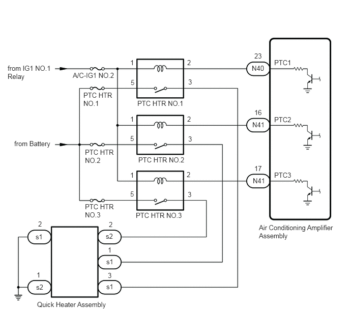
CAUTION / NOTICE / HINT
- NOTICE:
-
Inspect the fuses for circuits related to this system before performing the following procedure.
PROCEDURE
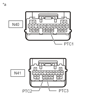
| *a | Front view of wire harness connector
(to Air Conditioning Amplifier Assembly) |
Disconnect the air conditioning amplifier assembly connectors.
Measure the voltage according to the value(s) in the table below.
- Standard Voltage:
Tester Connection Switch Condition Specified Condition N40-23 (PTC1) - Body ground Ignition switch off → ON Below 1 V → 11 to 14 V N41-16 (PTC2) - Body ground Ignition switch off → ON Below 1 V → 11 to 14 V N41-17 (PTC3) - Body ground Ignition switch off → ON Below 1 V → 11 to 14 V
- Result:
Proceed to OK NG
OK
NG
Connect the GTS to the DLC3.
Turn the ignition switch to ON.
Turn the GTS on.
Enter the following menus: Body Electrical / Air Conditioner / Active Test.
Perform the Active Test according to the display on the GTS.
- Body Electrical > Air Conditioner > Active Test
-
Tester Display Measurement Item Control Range Diagnostic Note Heater Active Level Quick heater assembly Min.: 0, Max.: 3 Perform this test when the following conditions are met:
·Engine running
·Air conditioning system is operated
- Body Electrical > Air Conditioner > Active Test
-
Tester Display Heater Active Level - 50004 121 33
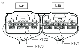
| *a | Component with harness connected
(Air Conditioning Amplifier Assembly) |
Measure the voltage according to the value(s) in the table below.
- Standard Voltage:
Tester Connection Condition Specified Condition N40-23 (PTC1) - Body ground ·Perform Active Test and select "OFF" → "ON" item
·Heater level is 1
11 to 14 V → Below 1 V N41-16 (PTC2) - Body ground ·Perform Active Test and select "OFF" → "ON" item
·Heater level is 2
11 to 14 V → Below 1 V N41-17 (PTC3) - Body ground ·Perform Active Test and select "OFF" → "ON" item
·Heater level is 3
11 to 14 V → Below 1 V
- Result:
Proceed to OK NG
OK
NG
Connect the GTS to the DLC3.
Turn the ignition switch to ON.
Turn the GTS on.
Enter the following menus: Body Electrical / Air Conditioner / Active Test.
Perform the Active Test according to the display on the GTS.
- Body Electrical > Air Conditioner > Active Test
-
Tester Display Measurement Item Control Range Diagnostic Note Heater Active Level Quick heater assembly Min.: 0, Max.: 3 Perform this test when the following conditions are met:
·Engine running
·Air conditioning system is operated
- Body Electrical > Air Conditioner > Active Test
-
Tester Display Heater Active Level - 50004 121 33
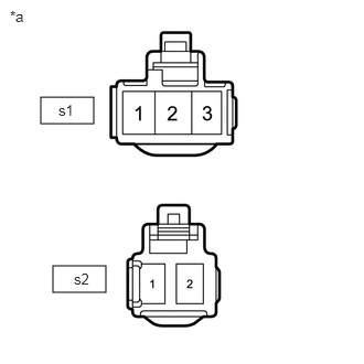
| *a | Front view of wire harness connector
(to Quick Heater Assembly) |
Disconnect the quick heater assembly connectors.
Measure the voltage according to the value(s) in the table below.
- Standard Voltage:
Tester Connection Condition Specified Condition s1-3 - Body ground ·Perform Active Test and select "OFF" → "ON" item
·Heater level is 1
Below 1 V → 11 to 14 V s1-1 - Body ground ·Perform Active Test and select "OFF" → "ON" item
·Heater level is 2
Below 1 V → 11 to 14 V s2-2 - Body ground ·Perform Active Test and select "OFF" → "ON" item
·Heater level is 3
Below 1 V → 11 to 14 V
- Result:
Proceed to OK NG
OK
NG
| *a | Front view of wire harness connector
(to Quick Heater Assembly) |
Disconnect the quick heater assembly connectors.
Measure the resistance according to the value(s) in the table below.
- Standard Resistance:
Tester Connection Condition Specified Condition s1-2 - Body ground Always Below 1 Ω s2-1- Body ground Always Below 1 Ω
- Result:
Proceed to OK NG
OK
NG
Remove the PTC heater relays (PTC HTR NO.1, PTC HTR NO.2 and PTC HTR NO.3) from the No. 2 engine room relay block assembly.
Inspect the PTC heater relays (PTC HTR NO.1, PTC HTR NO.2 and PTC HTR NO.3).
- Result:
Proceed to OK NG
OK
NG