HEATING / AIR CONDITIONING AIR CONDITIONING SYSTEM(for Manual Cooler System) Rear Blower Motor Circuit
DESCRIPTION
The blower motor assembly reads the signal and controls operation and speed changes of the blower motor.
If the blower air volume is weak, or there are any other blower malfunctions such as the temperature or air volume cannot be changed, the following causes are possible.
| Malfunction Status | Factor |
|---|---|
·
Blower does not operate at all. (No air comes out.) ·
Blower airflow volume cannot be changed. ·
Blower airflow volume is continuously weak. ·
Blower airflow volume is sometimes weak. |
Rear blower motor circuit malfunction |
WIRING DIAGRAM
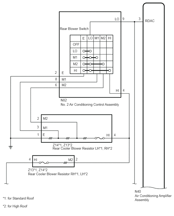
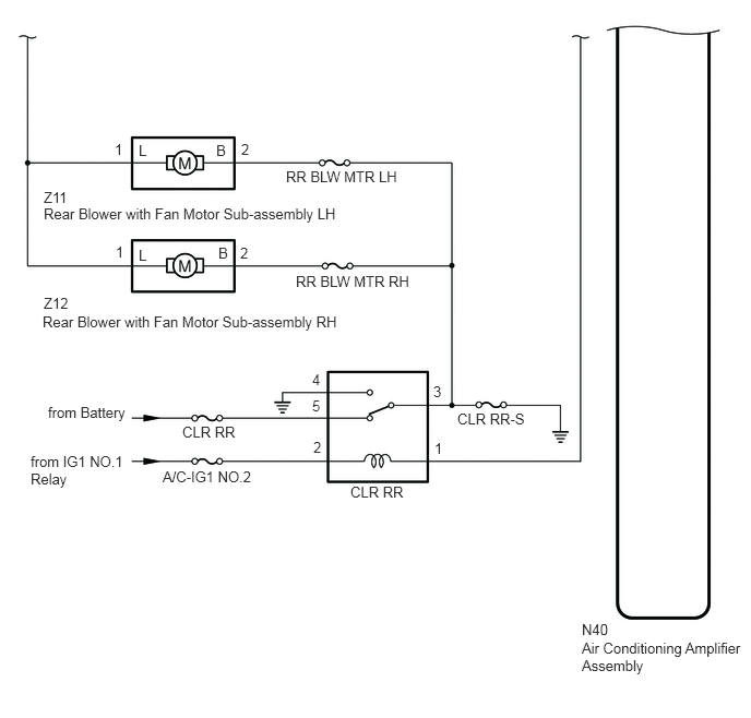
CAUTION / NOTICE / HINT
- NOTICE:
-
Inspect the fuses and relays for circuits related to this system before performing the following procedure.
PROCEDURE
Remove the cooler relay (CLR RR) from the No. 2 instrument panel junction block assembly.
Inspect the cooler relay (CLR RR).
- Result:
Proceed to OK NG
OK
NG
Remove the No. 2 air conditioning control assembly.
Inspect the No. 2 air conditioning control assembly.
- Result:
Proceed to OK NG
OK
NG
Inspect the rear cooler blower resistor.
- Result:
Proceed to OK NG
OK
NG
Remove the rear blower with fan motor sub-assembly.
Inspect the rear blower with fan motor sub-assembly.
- Result:
Proceed to OK NG
OK
NG
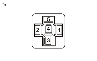
| *a | Front view of wire harness connector
(to Cooler Relay (CLR RR)) |
Remove the cooler relay (CLR RR) from the No. 1 instrument panel junction block assembly.
Measure the voltage according to the value(s) in the table below.
- Standard Voltage:
Tester Connection Condition Specified Condition Terminal 5 - Body ground Always 11 to 14 V Terminal 2 - Body ground Ignition switch off Below 1 V Terminal 2 - Body ground Ignition switch ON 11 to 14 V
Measure the resistance according to the value(s) in the table below.
- Standard Resistance:
Tester Connection Condition Specified Condition Terminal 4 - Body ground Always Below 1 Ω
- Result:
Proceed to OK NG
OK
NG
Remove the cooler relay (CLR RR) from the No. 1 instrument panel junction block assembly.
Disconnect the Z11 rear blower with fan motor sub-assembly LH connector.
Disconnect the Z12 rear blower with fan motor sub-assembly RH connector.
Measure the resistance according to the value(s) in the table below.
- Standard Resistance:
- for LH:
Tester Connection Condition Specified Condition Terminal 3 - Z11-2 (B) Always Below 1 Ω Terminal 3 - body ground Always Below 1 Ω Z11-2 (B) - body ground Always Below 1 Ω
- for RH:
Tester Connection Condition Specified Condition Terminal 3 - Z12-2 (B) Always Below 1 Ω Terminal 3 - body ground Always Below 1 Ω Z11-2 (B) - body ground Always Below 1 Ω
- Result:
Proceed to OK NG
OK
NG
Disconnect the Z11 rear blower with fan motor sub-assembly LH connector.
Disconnect the Z12 rear blower with fab motor sub-assembly RH connector.
for Standard Roof:
Disconnect the Z13 rear cooler blower resistor RH connector.
for High Roof:
Disconnect the Z14 rear cooler blower resistor LH connector.
Measure the resistance according to the value(s) in the table below.
- Standard Resistance:
- for LH (for Standard Roof):
Tester Connection Condition Specified Condition Z11-1 (L) - Z13-4 (HI) Always Below 1 Ω Z11-1 (L) or Z13-4 (HI) - Other terminals and body ground Always 10 kΩ or higher
- for LH (for High Roof):
Tester Connection Condition Specified Condition Z11-1 (L) - Z14-4 (HI) Always Below 1 Ω Z11-1 (L) or Z14-4 (HI) - Other terminals and body ground Always 10 kΩ or higher
- for RH (for Standard Roof):
Tester Connection Condition Specified Condition Z12-1 (L) - Z13-4 (HI) Always Below 1 Ω Z12-1 (L) or Z13-4 (HI) - Other terminals and body ground Always 10 kΩ or higher
- for RH (for High Roof):
Tester Connection Condition Specified Condition Z12-1 (L) - Z14-4 (HI) Always Below 1 Ω Z12-1 (L) or Z14-4 (HI) - Other terminals and body ground Always 10 kΩ or higher
- Result:
Proceed to OK NG
OK
NG
Disconnect the N82 No. 2 air conditioning control assembly connector.
Disconnect the Z14 rear cooler blower resistor LH connector.
Disconnect the Z13 rear cooler blower resistor RH connector.
Measure the resistance according to the value(s) in the table below.
- Standard Resistance:
- for Standard Roof:
Tester Connection Condition Specified Condition N82-4 (HI) - Z14-4 (HI) Always Below 1 Ω N82-4 (HI) - Z13-2 (M2) Always Below 1 Ω N82-4 (HI) or Z14-4 (HI) - Other terminals and body ground Always 10 kΩ or higher N82-4 (HI) or Z13-2 (M2) - Other terminals and body ground Always 10 kΩ or higher
- for High Roof:
Tester Connection Condition Specified Condition N82-4 (HI) - Z13-4 (HI) Always Below 1 Ω N82-4 (HI) - Z14-2 (M2) Always Below 1 Ω N82-4 (HI) or Z13-4 (HI) - Other terminals and body ground Always 10 kΩ or higher N82-4 (HI) or Z14-2 (M2) - Other terminals and body ground Always 10 kΩ or higher
- Result:
Proceed to OK NG
OK
NG
for Standard Roof:
Disconnect the Z14 rear cooler blower resistor LH connector.
for High Roof:
Disconnect the Z13 rear cooler blower resistor RH connector.
Disconnect the N82 No. 2 air conditioning control assembly connector.
Measure the resistance according to the value(s) in the table below.
- Standard Resistance:
- for Standard Roof:
Tester Connection Condition Specified Condition Z14-3 (M1) - N82-8 (M1) Always Below 1 Ω Z14-2 (M2) - N82-6 (M2) Always Below 1 Ω Z14-1 (E) - Body ground Always Below 1 Ω N82-2 (E) - Body ground Always Below 1 Ω Z14-3 (M1) or N82-8 (M1) - Other terminals and body ground Always 10 kΩ or higher Z14-2 (M2) or N82-6 (M2) - Other terminals and body ground Always 10 kΩ or higher
- for High Roof:
Tester Connection Condition Specified Condition Z13-3 (M1) - N82-8 (M1) Always Below 1 Ω Z13-2 (M2) - N82-6 (M2) Always Below 1 Ω Z13-1 (E) - Body ground Always Below 1 Ω N82-2 (E) - Body ground Always Below 1 Ω Z13-3 (M1) or N82-8 (M1) - Other terminals and body ground Always 10 kΩ or higher Z13-2 (M2) or N82-6 (M2) - Other terminals and body ground Always 10 kΩ or higher
- Result:
Proceed to OK NG
OK
NG
Disconnect the N40 air conditioning amplifier assembly connector.
Remove the cooler relay (CLR RR) from the No. 1 instrument panel junction block assembly.
Disconnect the N82 No. 2 air conditioning control assembly connector.
Measure the resistance according to the value(s) in the table below.
- Standard Resistance:
Tester Connection Condition Specified Condition N40-3 (RDAC) - N82-9 (LO) Always Below 1 Ω N40-3 (RDAC) - Terminal 1 Always Below 1 Ω N40-3 (RDAC) or N82-9 (LO) - Other terminals and body ground Always 10 kΩ or higher
- Result:
Proceed to OK NG
OK
NG