TIRE PRESSURE MONITORING TIRE PRESSURE WARNING VALVE INSTALLATION
CAUTION / NOTICE / HINT
- NOTICE:
- ·
Always use a new bolt, grommet, tubeless tire valve and valve core when installing the tire pressure warning valve and transmitter.
·Check that the washer and nut are not damaged, and replace them if necessary.
·Make sure not to damage the urethane covered backside of the tire pressure warning valve and transmitter (the surface opposite to the side with the ID code) with anything sharp.
·Write down the ID number before installation.
·Check that there is no oil, water or lubricant around the rim hole, tire pressure warning valve and transmitter, washer and nut. Failing to do so may result in improper installation.
·Use only a specified tire valve cap. If an unspecified tire valve cap is used, it may seize to the tire pressure warning valve and transmitter.
PROCEDURE

 42607
1.INSTALL TIRE PRESSURE WARNING VALVE AND TRANSMITTER
42607
1.INSTALL TIRE PRESSURE WARNING VALVE AND TRANSMITTER
Using a T10 "TORX" socket wrench, install the tire pressure monitor sensor to a new tubeless tire valve with a new bolt.
- Torque:
- 1.2 N*m (12 kgf*cm, 11 in.*lbf)
Install a new grommet to the tire pressure warning valve and transmitter.
- NOTICE:
-
Do not install a grommet to a new tire pressure warning valve and transmitter, as a new tire pressure warning valve and transmitter has a grommet already installed.
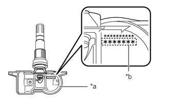
| *a | Printed Surface |
| *b | 7-digit Transmitter ID Number |
Record the 7-digit number transmitter ID printed on the tire pressure warning valve and transmitter at the position shown in the illustration.
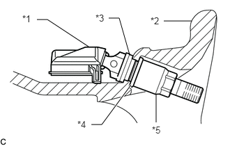
| *1 | Tire Pressure Warning Valve and Transmitter |
| *2 | Rim |
| *3 | Grommet |
| *4 | Washer |
| *5 | Nut |
Insert the tire pressure warning valve and transmitter into the valve installation hole from the inside of the rim so that the printed surface can be seen.
- NOTICE:
- ·
Check that there is no visible deformation, damage, or other abnormalities on the tire pressure warning valve and transmitter.
·Check that there is no foreign matter on the grommet and around the rim hole.
·If the tire pressure warning valve and transmitter is installed upside down, it may be damaged or fail to transmit signals when driving at high speeds.
·Use a tire pressure warning valve and transmitter with a part number that matches that of the vehicle.
From the outside of the rim, install the washer to the tire pressure warning valve and transmitter, which has the grommet installed. Afterward, using an 11 mm deep socket wrench, tighten the nut.
- Torque:
- 4.0 N*m (41 kgf*cm, 35 in.*lbf)
- NOTICE:
- ·
No further tightening is required once the nut is tightened to the specified torque.
·Check that there is no foreign matter on the washer and nut.
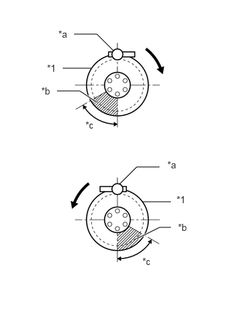
| *1 | Rim |
| *a | Mount Tool of Mounting Machine |
| *b | Area for Tire Pressure Warning Valve and Transmitter |
| *c | 60° |

|
Rim Rotation Direction |
Set the tire and disc wheel onto the mounting machine.
- NOTICE:
- ·
Make sure the tire pressure warning valve and transmitter is positioned in the area shown in the illustration when set to the mounting machine. Otherwise, the tire pressure warning valve and transmitter may interfere with the tire bead and become damaged.
·Position the main body of the tire pressure warning valve and transmitter in the area shown in the illustration.
Apply a sufficient coat of soapy water or equivalent to the tire bead and rim.
- NOTICE:
-
Do not apply soapy water or equivalent directly to the tire pressure warning valve and transmitter.
Using a mounting machine, install the tire to the disc wheel.
- NOTICE:
- ·
Make sure that the tire bead and mount tool do not interfere with the tire pressure warning valve and transmitter.
·Make sure that the tire pressure warning valve and transmitter is not clamped by the bead and rim.
Install a new valve core.
Adjust the tire pressure to the standard tire pressure.
After the tire is inflated, the valve nut may be loose. Using an 11 mm deep socket wrench, retighten the nut to the specified torque.
- Torque:
- 4.0 N*m (41 kgf*cm, 35 in.*lbf)
- NOTICE:
-
No further tightening is required once the nut is tightened to the specified torque.
Check the surroundings of the tire pressure warning valve and transmitter for air leaks with soapy water or equivalent.
If air is leaking from the valve core, press the valve core several times to remove foreign matter. Replace the valve core as necessary.
If air is leaking from around the tire pressure warning valve and transmitter, check if the grommet, washer and nut are not deformed, damaged or contaminated with foreign matter. Replace the grommet, washer or nut as necessary.
Install the valve cap.
2.INSTALL FRONT WHEEL
3.INSTALL REAR WHEEL
4.INSTALL SPARE TIRE
5.INSPECT TIRES
6. REGISTRATION OF TRANSMITTER ID
7.INSPECT TIRE PRESSURE WARNING SYSTEM