☰ Toyota HiAce☰ فهرستVehicle Interior › HEATING / AIR CONDITIONING › AIR CONDITIONING SYSTEM(for Automatic Air Conditioning System)
RM35X0E
_58
Vehicle Interior
_079316
HEATING / AIR CONDITIONING
_0386651
AIR CONDITIONING SYSTEM(for Automatic Air Conditioning System)
J
HEATING / AIR CONDITIONING AIR CONDITIONING SYSTEM(for Automatic Air Conditioning System) Idle Up Switch Circuit
DESCRIPTION
When the idle up switch is pushed, the air conditioning amplifier assembly outputs the engine idle up signal. If engine idle up does not occur when the idle up switch is pushed, there may be a problem in the circuit shown below.
| Malfunction Status | Factor |
|---|---|
| Engine idle up does not occur when idle up switch is pushed while engine is cold. | Idle up switch circuit malfunction |
WIRING DIAGRAM
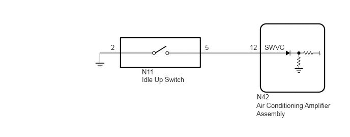
5.417,0.885 6.031,1.083
0.615,0.198
10
false
SWVC
5.115,0.885 5.333,1.083
0.219,0.198
10
false
12
4.198,0.885 4.417,1.083
0.219,0.198
10
false
5
2.271,0.885 2.49,1.083
0.219,0.198
10
false
2
2.906,1.385 3.281,1.583
0.375,0.198
10
false
N11
2.906,1.542 3.906,1.74
1,0.198
10
false
Idle Up Switch
5.26,1.896 5.635,2.094
0.375,0.198
10
false
N42
5.25,2.073 6.813,2.604
1.563,0.531
10
false
Air Conditioning Amplifier Assembly
PROCEDURE
1.READ VALUE USING GTS (IDLE UP/PWR HEAT SWITCH)
a.
Connect the GTS to the DLC3.
b.
Turn the ignition switch to ON.
c.
Turn the GTS on.
d.
Enter the following menus: Body Electrical / Air Conditioner / Data List.
e.
Check the value(s) by referring to the table below.
- Body Electrical > Air Conditioner > Data List
-
Tester Display Measurement Item Range Normal Condition Diagnostic Note IDLE UP/PWR HEAT Switch Idle up switch ON or OFF ON: Idle up switch on
OFF: Idle up switch off-
- Body Electrical > Air Conditioner > Data List
-
Tester Display IDLE UP/PWR HEAT Switch - 50003 121 173
- OK:
The display is as specified in the normal condition column.
- Result:
Proceed to OK NG
OK
REPLACE AIR CONDITIONING AMPLIFIER ASSEMBLY
NG
2.INSPECT IDLE UP SWITCH
2.INSPECT IDLE UP SWITCH
a.
Remove the idle up switch.
b.
Inspect the idle up switch.
- Result:
Proceed to OK NG
OK
3.CHECK HARNESS AND CONNECTOR (IDLE UP SWITCH - AIR CONDITIONING AMPLIFIER ASSEMBLY AND BODY GROUND)
NG
REPLACE IDLE UP SWITCH
3.CHECK HARNESS AND CONNECTOR (IDLE UP SWITCH - AIR CONDITIONING AMPLIFIER ASSEMBLY AND BODY GROUND)
a.
Disconnect the N11 idle up switch connector.
b.
Disconnect the N42 air conditioning amplifier assembly connector.
c.
Measure the resistance according to the value(s) in the table below.
- Standard Resistance:
Tester Connection Condition Specified Condition N11-5 - N42-12 (SWVC) Always Below 1 Ω N11-2 - Body ground Always Below 1 Ω N11-5 or N42-12 (SWVC) - Body ground Always 10 kΩ or higher
- Result:
Proceed to OK NG
OK
REPLACE AIR CONDITIONING AMPLIFIER ASSEMBLY
NG
REPAIR OR REPLACE HARNESS OR CONNECTOR