PARK ASSIST / MONITORING REAR VIEW MONITOR SYSTEM(for Inner Rear View Mirror Type) Reverse Signal Circuit
DESCRIPTION
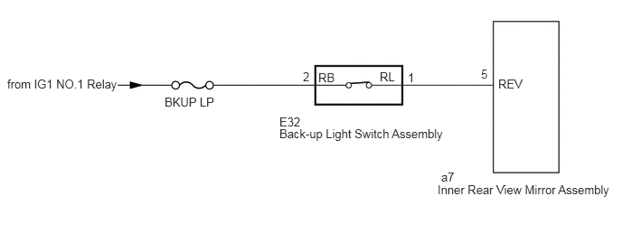
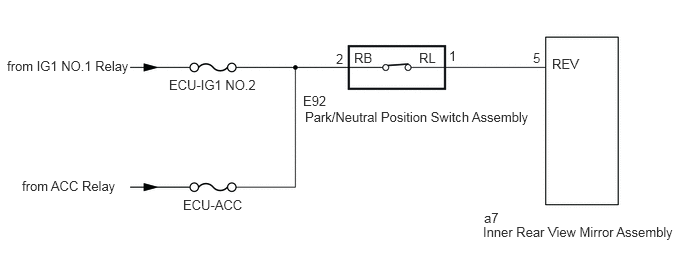
The inner rear view mirror assembly receives a reverse signal from the back-up light switch assembly*1 or the park/neutral position switch assembly*2.
*1: for Manual Transmission
*2: for Automatic Transmission
WIRING DIAGRAM
CAUTION / NOTICE / HINT
- NOTICE:
-
Inspect the fuses for circuits related to this system before performing the following procedure.
PROCEDURE
- Result:
Result Proceed to for Manual Transmission A for Automatic Transmission B
A
B
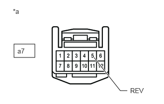
| *a | Front view of wire harness connector
(to Inner Rear View Mirror Assembly) |
Disconnect the inner rear view mirror assembly connector.
Measure the voltage according to the value(s) in the table below.
- Standard Voltage:
Tester Connection Condition Specified Condition a7-5 (REV) - Body ground Ignition switch ON, shift lever in R 11 to 14 V a7-5 (REV) - Body ground Ignition switch ON, shift lever not in R Below 1 V
- Result:
Proceed to OK NG
OK
NG
Remove the back-up light switch assembly.
Inspect the back-up light switch assembly.
- Result:
Proceed to OK NG
OK
NG
Disconnect the E32 back-up light switch assembly connector.
Disconnect the a7 inner rear view mirror assembly connector.
Measure the voltage according to the value(s) in the table below.
- Standard Voltage:
Tester Connection Switch Condition Specified Condition E32-2 (RB) - Body ground Ignition switch ON 11 to 14 V
Measure the resistance according to the value(s) in the table below.
- Standard Resistance:
Tester Connection Condition Specified Condition E32-1 (RL) - a7-5 (REV) Always Below 1 Ω E32-1 (RL) - Body ground Always 10 kΩ or higher
- Result:
Proceed to OK NG
OK
NG
| *a | Front view of wire harness connector
(to Inner Rear View Mirror Assembly) |
Disconnect the inner rear view mirror assembly connector.
Measure the voltage according to the value(s) in the table below.
- Standard Voltage:
Tester Connection Condition Specified Condition a7-5 (REV) - Body ground Ignition switch ON, shift lever in R 11 to 14 V a7-5 (REV) - Body ground Ignition switch ON, shift lever not in R Below 1 V
- Result:
Proceed to OK NG
OK
NG
Remove the park/neutral position switch assembly.
Inspect the park/neutral position switch assembly.
- Result:
Proceed to OK NG
OK
NG
Disconnect the E92 park/neutral position switch assembly connector.
Disconnect the a7 inner rear view mirror assembly connector.
Measure the voltage according to the value(s) in the table below.
- Standard Voltage:
Tester Connection Switch Condition Specified Condition E92-2 (RB) - Body ground Ignition switch ON 11 to 14 V
Measure the resistance according to the value(s) in the table below.
- Standard Resistance:
Tester Connection Condition Specified Condition E92-1 (RL) - a7-5 (REV) Always Below 1 Ω E92-1 (RL) - Body ground Always 10 kΩ or higher
- Result:
Proceed to OK NG
OK
NG