PARK ASSIST / MONITORING BLIND SPOT MONITOR SYSTEM Buzzer does not Sound
WIRING DIAGRAM
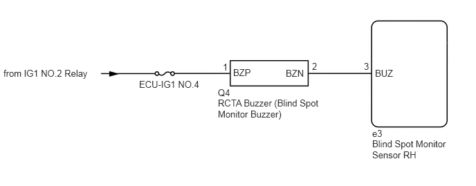
CAUTION / NOTICE / HINT
- NOTICE:
-
Inspect the fuses for circuits related to this system before performing the following procedure.
PROCEDURE
Clear the DTCs.
- Body Electrical > Blind Spot Monitor Slave > Clear DTCs
- 50002 314
Recheck for DTCs and check if the same DTC is output again.
- Body Electrical > Blind Spot Monitor Slave > Trouble Codes
- 50001 314
- OK:
No DTCs are output.
- Result:
Proceed to OK NG
OK
NG
Disconnect the Q4 RCTA buzzer (blind spot monitor buzzer) connector.
Disconnect the e3 blind spot monitor sensor RH connector.
Measure the voltage according to the value(s) in the table below.
- Standard Voltage:
Tester Connection Switch Condition Specified Condition Q4-1 (BZP) - Body ground Ignition switch ON 11 to 14 V Q4-2 (BZN) or e3-3 (BUZ) - Body ground Ignition switch ON Below 1 V Q4-2 (BZN) - Q4-1 (BZP) Ignition switch ON Below 1 V
- Result:
Proceed to OK NG
OK
NG
Disconnect the Q4 RCTA buzzer (blind spot monitor buzzer) connector.
Disconnect the e3 blind spot monitor sensor RH connector.
Measure the resistance according to the value(s) in the table below.
- Standard Resistance:
Tester Connection Condition Specified Condition Q4-2 (BZN) - e3-3 (BUZ) Always Below 1 Ω Q4-2 (BZN) or e3-3 (BUZ) - Body ground Always 10 kΩ or higher
Measure the voltage according to the value(s) in the table below.
- Standard Voltage:
Tester Connection Switch Condition Specified Condition Q4-2 (BZN) or e3-3 (BUZ) - Body ground Ignition switch ON Below 1 V Q4-1 (BZP) - Body ground Ignition switch ON 11 to 14 V Q4-1 (BZP) - Body ground Ignition switch off Below 1 V
- Result:
Proceed to OK NG
OK
NG
Replace the RCTA buzzer (blind spot monitor buzzer) with a new or known good one and check if the same malfunction recurs.
- OK:
Malfunction does not reoccur (returns to normal).
- Result:
Proceed to OK NG
OK
NG