AC60E AUTOMATIC TRANSMISSION / TRANSAXLE AUTOMATIC TRANSMISSION SYSTEM(for 7GR-FKS) P071011 Transmission Fluid Temperature Sensor "A" Circuit Short To Ground
DESCRIPTION
The No. 1 ATF temperature sensor converts the fluid temperature into a resistance value for use by the ECM.
The ECM applies a voltage to the temperature sensor through terminal THO1 of the ECM.
The sensor resistance changes with the ATF temperature. As the temperature becomes higher, the sensor resistance decreases.
One terminal of the sensor is grounded so that the sensor resistance decreases and the voltage goes down as the temperature becomes higher.
The ECM calculates the fluid temperature based on the voltage signal.
| DTC No. | Detection Item | DTC Detection Condition | Trouble Area | MIL | Memory | Note |
|---|---|---|---|---|---|---|
| P071011 | Transmission Fluid Temperature Sensor "A" Circuit Short To Ground | The output voltage from the No. 1 ATF temperature sensor is below 0.142 V for 0.5 seconds or more (1 trip detection logic). | ·
Short in No. 1 ATF temperature sensor circuit ·
No. 1 ATF temperature sensor (transmission wire) ·
ECM |
Comes on | DTC stored | SAE Code:
P0712 |
MONITOR DESCRIPTION
The No. 1 ATF temperature sensor converts the ATF temperature to an electrical resistance value. Based on the resistance, the ECM determines the ATF temperature and detects a short in the No. 1 ATF temperature sensor circuit. If the resistance value of the No. 1 ATF temperature sensor is below 79 Ω*, the ECM interprets this as a fault in the No. 1 ATF temperature sensor or wiring. The ECM will illuminate the MIL and store the DTC.
*: 150°C (302°F) or more is indicated regardless of the actual ATF temperature.
- HINT:
-
The ATF temperature can be checked on the GTS display.
CONFIRMATION DRIVING PATTERN
- HINT:
-
After repairs have been completed, clear the DTCs and then check that the vehicle has returned to normal by performing the following All Readiness check procedure.
Connect the GTS to the DLC3.
Turn the ignition switch to ON and turn the GTS on.
Clear the DTCs (even if no DTCs are stored, perform the clear DTC procedure).
Turn the ignition switch off and wait for at least 30 seconds.
Turn the ignition switch to ON and turn the GTS on.
Wait for 3 seconds or more with the ignition switch ON.
Enter the following menus: Powertrain / Transmission / Utility / All Readiness.
Input the DTC: P071011.
Check the DTC judgment result.
| GTS Display | Description |
|---|---|
| NORMAL | ·
DTC judgment completed ·
System normal |
| ABNORMAL | ·
DTC judgment completed ·
System abnormal |
| INCOMPLETE | ·
DTC judgment not completed ·
Perform driving pattern after confirming DTC enabling conditions |
| N/A | ·
Unable to perform DTC judgment ·
Number of DTCs which do not fulfill DTC preconditions has reached ECU memory limit |
- HINT:
- ·
If the judgment result shows NORMAL, the system is normal.
·If the judgment result shows ABNORMAL, the system has a malfunction.
·If the judgment result shows INCOMPLETE or N/A, perform the Confirmation Driving Pattern and check the DTC judgment result again.
WIRING DIAGRAM

CAUTION / NOTICE / HINT
- NOTICE:
-
Perform registration and/or initialization when parts related to the automatic transmission are replaced.
DATA LIST
- HINT:
-
Using the GTS to read the Data List allows the values or states of switches, sensors, actuators and other items to be read without removing any parts. This non-intrusive inspection can be very useful because intermittent conditions or signals may be discovered before parts or wiring is disturbed. Reading the Data List information early in troubleshooting is one way to save diagnostic time.
- NOTICE:
-
In the table below, the values listed under "Normal Condition" are reference values. Do not depend solely on these reference values when deciding whether a part is faulty or not.
Warm up the engine.
Turn the ignition switch off.
Connect the GTS to the DLC3.
Turn the ignition switch to ON.
Turn the GTS on.
Enter the following menus: Powertrain / Transmission / Data List / A/T Oil Temperature No.1.
Read the Data List according to the display on the GTS.
- Powertrain > Transmission > Data List
-
Tester Display Measurement Item Range Normal Condition Diagnostic Note A/T Oil Temperature No.1 No. 1 ATF temperature sensor value Min.: -40°C (-40°F)
Max.: 150°C (302°F)·Approx. 80°C (176°F): After stall test
·Equal to ambient temperature when cold soak
If the value -40°C (-40°F) or 150°C (302°F), No. 1 ATF temperature sensor circuit is open or shorted.
- Powertrain > Transmission > Data List
-
Tester Display A/T Oil Temperature No.1 - 50003 373 180
- HINT:
- ·
When DTC P071011 is output and the GTS shows 150°C (302°F) or higher, there is a short circuit.
·When DTC P071015 is output and the GTS shows -40°C (-40°F), there is an open circuit.
Check the temperature displayed on the GTS in order to check if a malfunction exists.
Temperature Displayed Malfunction -40°C (-40°F) Open circuit 150°C (302°F) or higher Short circuit
PROCEDURE
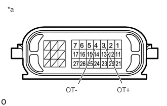
| *a | Component without harness connected
(Transmission Wire) |
Disconnect the transmission wire connector.
Measure the resistance according to the value(s) in the table below.
- Standard Resistance:
Tester Connection Condition Specified Condition 3 (OT+) - 4 (OT-) Always 79 Ω to 156 kΩ 3 (OT+) - Body ground and other terminals Always 10 kΩ or higher 4 (OT-) - Body ground and other terminals Always 10 kΩ or higher
- HINT:
-
If the resistance is out of the specified range at any of the ATF temperatures shown in the table below, the driveability of the vehicle may decrease.
ATF Temperature Specified Condition 10°C (50°F) 5 to 8 kΩ 25°C (77°F) 2.5 to 4.5 kΩ 110°C (230°F) 0.22 to 0.28 kΩ
- Result:
Proceed to OK NG
OK
NG
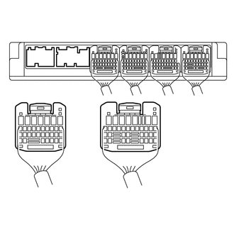
| *a | Rear view of wire harness connector
(to ECM) |
Disconnect the ECM connectors.
Measure the resistance according to the value(s) in the table below.
- Standard Resistance:
Tester Connection Condition Specified Condition E2-26 (THO1) - E1-23 (ETHW) Always 79 Ω to 156 kΩ
- Result:
Proceed to OK NG
OK
NG