BRAKE CONTROL / DYNAMIC CONTROL SYSTEMS ELECTRONICALLY CONTROLLED BRAKE SYSTEM(w/ VSC OFF Switch) PRECAUTION
TROUBLESHOOTING PRECAUTION
When there is a malfunction with terminal contact points or part installation problems, removal and installation of the suspected parts may return the system to normal either completely or temporarily.
Before disconnecting any connector or removing and installing parts, check and record DTCs and freeze frame data as it may be useful for determining the malfunctioning area by providing vehicle operation data at the time of the malfunction.
If any open circuit DTCs related to intermittent (momentary interruptions) malfunctions are output, check the intermittent monitor.
Since the system may be influenced by malfunctions in systems other than the electronically controlled brake system, be sure to check for DTCs in other systems.
HANDLING PRECAUTION
Always ensure that the ignition switch is off before removing the brake actuator assembly or a sensor unless specifically instructed by the repair manual.
When replacing the brake actuator assembly, always replace it with a new one.
- NOTICE:
-
Never use a brake actuator assembly from another vehicle, including new vehicles.
If the brake actuator assembly or a sensor has been removed and installed, always perform a Dealer Mode (Signal Check) inspection and check for DTCs after completion of installation to confirm that the system is operating correctly.
Do not remove and install any electronically controlled brake system components not specified by the repair manual or the system may not operate correctly due to loss of calibration.
When performing diagnosis and repair for the electronically controlled brake system, follow all specified procedures and perform the necessary inspections after completion.
DTC PRECAUTION
If the warning lights are illuminated due to a malfunction, the warning lights will only turn off for some DTCs when the malfunction is repaired and the DTCs are cleared.
If a warning lights are illuminated, it is necessary to follow the procedure to turn off the warning lights.
- NOTICE:
- ·
Use caution when operating the vehicle when the warning lights are illuminated as the system may not operate due to a fail-safe function.
·After clearing the DTCs, the DTCs will be stored again if the malfunction persists.
CHASSIS DYNAMOMETER PRECAUTION
When testing with a 2-wheel drum tester such as speedometer tester, combination tester for the speedometer and brakes, or chassis dynamometer, or when jacking up the front wheels and turning the wheels, perform the following procedure to enter Inspection Mode and disable the TRC, AUTO LSD and VSC systems.
for entering inspection mode: Click hereBrake>BRAKE CONTROL / DYNAMIC CONTROL SYSTEMS>ELECTRONICALLY CONTROLLED BRAKE SYSTEM (w/ VSC OFF Switch)>UTILITY201902,999999,_54,_078667,_0385049,RM100000001GK1P,
- CAUTION:
- ·
Do not use the drum tester with any of the lock chains disconnected.
·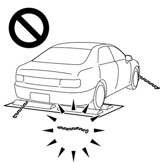
Using the drum tester with a lock chain disconnected could cause the vehicle to begin moving unexpectedly.
·Do not use the drum tester while the TRC, AUTO LSD or VSC is able to operate.
·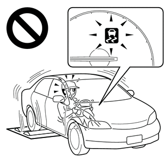
TRC, AUTO LSD or VSC operation could cause the vehicle to begin moving unexpectedly.
DISABLING AND ENABLING OF AUTO LSD AND VSC BY OPERATION OF VSC OFF SWITCH
Switching of mode
Operating the VSC OFF switch switches the system between normal mode, AUTO LSD mode and VSC off mode.
Normal mode
If the VSC OFF switch is pressed when in AUTO LSD mode or VSC off mode, the system enters normal mode.
In normal mode, TRC and VSC are enabled.
The system is set to normal mode when the ignition switch is turned to ON.
AUTO LSD mode
If the VSC OFF switch is pressed when the vehicle speed is 50 km/h or less, the system enters AUTO LSD mode.
In AUTO LSD mode, the AUTO LSD indicator light and VSC OFF indicator light in the combination meter illuminate and AUTO LSD operation is permitted.
When the vehicle speed increases during AUTO LSD mode, the vehicle does not return to normal mode.
VSC off mode
for Multi-information Display Type:
When the VSC OFF switch is pressed and held for 3 seconds or more with the vehicle stopped, the system enters VSC off mode. When in VSC off mode, TRC and VSC are disabled, the multi-information display in the combination meter assembly displays "TRC OFF message" and the VSC OFF indicator light is illuminated.
The system does not automatically return to normal mode based on vehicle speed when in VSC off mode.
except Multi-information Display Type:
When the VSC OFF switch is pressed and held for 3 seconds or more with the vehicle stopped, the system enters VSC off mode. When in VSC off mode, TRC and VSC are disabled and the TRC OFF indicator and VSC OFF indicator lights illuminate.
The system does not automatically return to normal mode based on vehicle speed when in VSC off mode.
CAN COMMUNICATION SYSTEM PRECAUTION
The CAN communication system is used for communication between the skid control ECU (brake actuator assembly), steering sensor, yaw rate and acceleration sensor (airbag ECU assembly) and other ECUs. If there is a malfunction in a CAN communication line, communication DTCs related to the affected systems will be stored.
If any CAN communication DTCs are output, repair the malfunction, then troubleshoot the electronically controlled brake system while communication is normal.
In order to enable CAN communication, a specific type of wiring is used for the CAN communication lines. The wiring used for each communication line is a twisted pair of wires that have an equal length. A bypass wire should not be used because the data being transmitted will be corrupted.