AUDIO / VIDEO AUDIO AND VISUAL SYSTEM(for Radio Receiver Type) Vehicle Speed Signal Circuit between Radio Receiver and Combination Meter
DESCRIPTION
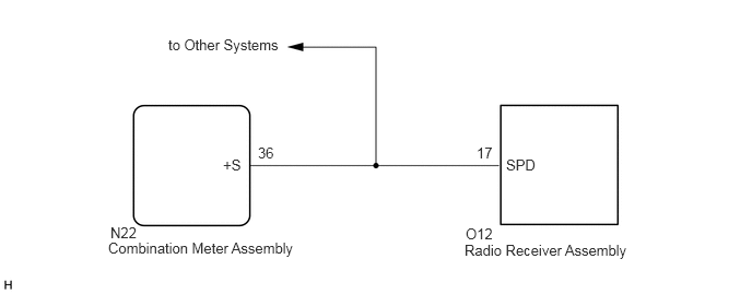
The radio receiver assembly receives a vehicle speed signal from the combination meter assembly to control the ASL function.
- HINT:
- ·
A voltage of 12 V or 5 V is output from each ECU and then input to the combination meter assembly. The signal is changed to a pulse signal at the transistor in the combination meter assembly. Each ECU controls its respective system based on this pulse signal.
·If a short occurs in any of the ECUs or in the wire harness connected to an ECU, all systems in the diagram below will not operate normally.
WIRING DIAGRAM
CAUTION / NOTICE / HINT
- NOTICE:
-
The audio and visual system troubleshooting procedure is based on the premise that the meter / gauge system is operating normally. Check the meter / gauge system first before troubleshooting the audio and visual system.
PROCEDURE
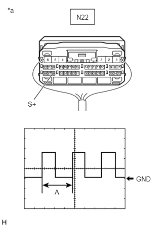
| *a | Component with harness connected
(Combination Meter Assembly) |
Check the output waveform.
Remove the combination meter assembly with the connector still connected.
Connect an oscilloscope to terminal N22-36 (+S) and body ground.
Turn the ignition switch to ON.
Turn a wheel slowly.
Check the signal waveform according to the condition(s) in the table below.
| Item | Condition |
|---|---|
| Measurement terminal | N22-36 (+S) - Body ground |
| Tool setting | 5 V/DIV, 20 ms./DIV |
| Vehicle condition | Wheel being rotated |
- OK:
The waveform is similar to that shown in the illustration.
- HINT:
-
When the system is functioning normally, one wheel revolution generates 4 pulses. As the vehicle speed increases, the width indicated by (A) in the illustration narrows.
- Result:
Proceed to OK NG
OK
NG
Disconnect the O12 radio receiver assembly connector.
Disconnect the N22 combination meter assembly connector.
Measure the resistance according to the value(s) in the table below.
- Standard Resistance:
Tester Connection Condition Specified Condition O12-17 (SPD) - N22-36 (+S) Always Below 1 Ω
- Result:
Proceed to OK NG
OK
NG