☰ Toyota HiAce☰ فهرستAudio / Visual / Telematics › AUDIO / VIDEO › AUDIO AND VISUAL SYSTEM(for Radio Receiver Type)
RM35X0E
_56
Audio / Visual / Telematics
_078377
AUDIO / VIDEO
_0383454
AUDIO AND VISUAL SYSTEM(for Radio Receiver Type)
J
AUDIO / VIDEO AUDIO AND VISUAL SYSTEM(for Radio Receiver Type) Dimmer Signal Circuit
DESCRIPTION
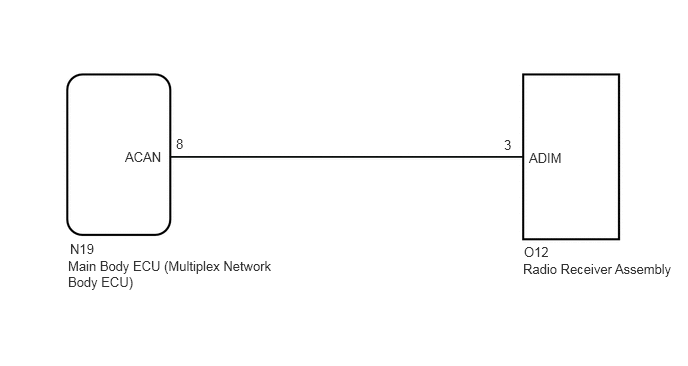
The main body ECU (multiplex network body ECU) sends an auto dimmer signal to the radio receiver assembly via this circuit.
When the radio receiver assembly receives an auto dimmer signal from the main body ECU (multiplex network body ECU), the radio receiver assembly causes the instrument panel illumination to be dimmed.
WIRING DIAGRAM
5.448,2.719 7.115,3.01
1.667,0.292
10
false
Radio Receiver Assembly
0.708,2.688 2.896,3.26
2.188,0.573
10
false
Main Body ECU (Multiplex Network Body ECU)
1.302,1.552 1.792,1.75
0.49,0.198
10
false
ACAN
5.51,1.563 6.031,1.76
0.521,0.198
10
false
ADIM
5.458,2.542 5.885,2.76
0.427,0.219
10
false
O12
5.25,1.427 5.448,1.615
0.198,0.188
10
false
3
1.833,1.417 2.031,1.604
0.198,0.188
10
false
8
0.729,2.51 1.156,2.729
0.427,0.219
10
false
N19
PROCEDURE
1.CHECK MAIN BODY ECU (MULTIPLEX NETWORK BODY ECU)
a.
Disconnect the radio receiver assembly connector.
b.
1.5,0.521 1.917,0.833
0.417,0.313
0.729,1.125 0.906,1.125
0.906,1.125 1.052,1.802
true
1.594,0.594 2.052,0.792
0.458,0.198
10
false
O12
0.083,0.083 0.542,0.281
0.458,0.198
10
false
*a
0.354,1.042 0.813,1.24
0.458,0.198
10
false
ADIM
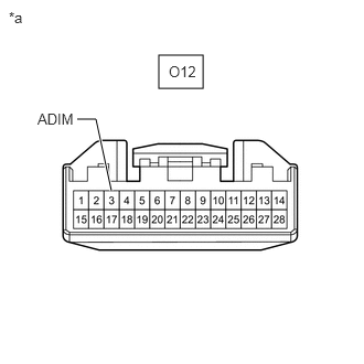
| *a | Front view of wire harness connector
(to Radio Receiver Assembly) |
Measure the voltage according to the value(s) in the table below.
- Standard Voltage:
Tester Connection Condition Specified Condition O12-3 (ADIM) - Body ground Ignition switch ON, automatic light control sensor covered by hand, and light control switch in AUTO position 11 to 14 V
- Result:
Proceed to OK NG
OK
PROCEED TO NEXT SUSPECTED AREA SHOWN IN PROBLEM SYMPTOMS TABLE
NG
2.CHECK HARNESS AND CONNECTOR (RADIO RECEIVER ASSEMBLY - MAIN BODY ECU [MULTIPLEX NETWORK BODY ECU])
2.CHECK HARNESS AND CONNECTOR (RADIO RECEIVER ASSEMBLY - MAIN BODY ECU [MULTIPLEX NETWORK BODY ECU])
a.
Disconnect the N19 main body ECU (multiplex network body ECU) connector.
b.
Disconnect the O12 radio receiver assembly connector.
c.
Measure the resistance according to the value(s) in the table below.
- Standard Resistance:
Tester Connection Condition Specified Condition N19-8 (ACAN) - O12-3 (ADIM) Always Below 1 Ω
- Result:
Proceed to OK NG
OK
REPLACE MAIN BODY ECU (MULTIPLEX NETWORK BODY ECU)
NG
REPAIR OR REPLACE HARNESS OR CONNECTOR