TELEMATICS MAYDAY SWITCH INSPECTION
PROCEDURE

 1.REMOVE MAP LIGHT ASSEMBLY
2.INSPECT MAYDAY SWITCH (MAP LIGHT ASSEMBLY)
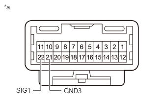
| *a | Component without harness connected
(Mayday Switch (Map Light Assembly)) |
Measure the resistance according to the value(s) in the table below.
- Standard Resistance:
Tester Connection Condition Specified Condition 22 (SIG1) - 21 (GND3) Manual (SOS) switch not pressed 408 to 416 Ω 22 (SIG1) - 21 (GND3) Manual (SOS) switch pressed 81 to 83 Ω
If the result is not as specified, replace the mayday switch (map light assembly).
Inspect the operation (red indicator)
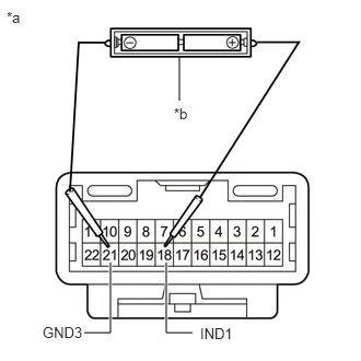
| *a | Component without harness connected
(Mayday Switch (Map Light Assembly)) |
| *b | Two 1.5 V dry cell batteries |
Check that each indicator illuminates when 2 dry cell batteries are connected to the map light assembly connector terminals as shown in the illustration.
- OK:
Battery Connection Specified Condition 18 (IND1) - Battery positive (+)
21 (GND3) - Battery negative (-)Red indicator comes on
- NOTICE:
-
Do not apply more than 3 V.
If the result is not as specified, replace the mayday switch (map light assembly).
Inspect the operation (green indicator)
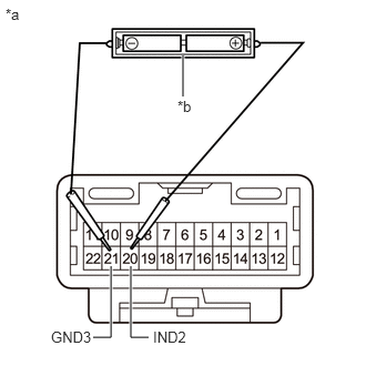
| *a | Component without harness connected
(Mayday Switch (Map Light Assembly)) |
| *b | Two 1.5 V dry cell batteries |
Check that each indicator illuminates when 2 dry cell batteries are connected to the map light assembly connector terminals as shown in the illustration.
- OK:
Battery Connection Specified Condition 20 (IND2) - Battery positive (+)
21 (GND3) - Battery negative (-)Green indicator comes on
- NOTICE:
-
Do not apply more than 3 V.
If the result is not as specified, replace the mayday switch (map light assembly).
Inspect the operation (HELP indicator)
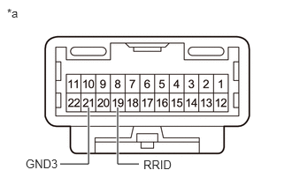
| *a | Component without harness connected
(Mayday Switch (Map Light Assembly)) |
Check that each indicator illuminates when auxiliary battery are connected to the mayday switch (map light assembly) connector terminals.
- OK:
Battery Connection Specified Condition 19 (RRID) - Battery positive (+)
21 (GND3) - Battery negative (-)HELP indicator comes on
If the result is not as specified, replace the mayday switch (map light assembly).
3.INSTALL MAP LIGHT ASSEMBLY