DOOR / HATCH POWER SLIDE DOOR SYSTEM TERMINALS OF ECU
CHECK SLIDE DOOR MOTOR UNIT RH (SLIDE DOOR ECU RH)
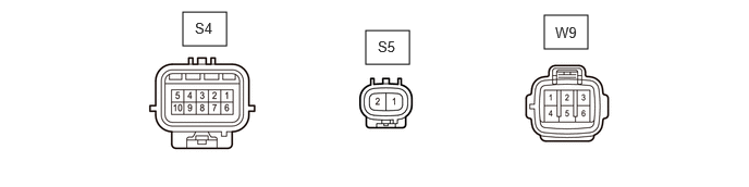
Disconnect the S4 and W9 slide door motor unit RH (slide door ECU RH) connectors.
Measure the voltage and resistance according to the value(s) in the table below.
| Tester Connection | Wiring Color | Terminal Description | Condition | Specified Condition |
|---|---|---|---|---|
| W9-3 (B) - Body ground | L - Body ground | Power supply | Always | 11 to 14 V |
| W9-2 (MSW) - Body ground | GR - Body ground | Power slide door main switch signal | Power slide door main switch on → off | Below 1 Ω → 10 kΩ or higher |
| W9-1 (GND) - Body ground | W-B - Body ground | Ground | Always | Below 1 Ω |
| W9-6 (ECUB) - Body ground | GR - Body ground | Power supply | Always | 11 to 14 V |
| S4-2 (OSG) - Body ground | W - Body ground | Power slide door sensor assembly RH ground | Always | Below 1 Ω |
| S4-7 (DS2) - Body ground | LG - Body ground | Slide door lock remote control assembly RH (open switch) signal | Inside handle or outside handle not operated → inside handle or outside handle operated to open side | 10 kΩ or higher → Below 1 Ω |
| S4-8 (DS1) - Body ground | L - Body ground | Slide door lock remote control assembly RH (close switch) signal | Inside handle or outside handle not operated → inside handle or outside handle operated to close side | 10 kΩ or higher → Below 1 Ω |
| S4-10 (OS) - S4-2 (OSG) | GR - W | Power slide door sensor assembly RH signal | Power slide door sensor assembly RH pushed → not pushed | Below 100 Ω → 1 kΩ or higher |
Reconnect the S4 and W9 slide door motor unit RH (slide door ECU RH) connectors.
Measure the voltage and resistance according to the value(s) in the table below.
| Tester Connection | Wiring Color | Terminal Description | Condition | Specified Condition |
|---|---|---|---|---|
| S4-2 (OSG) - Body ground | W - Body ground | Power slide door sensor assembly RH ground | Always | Below 1 Ω |
CHECK SLIDE DOOR MOTOR UNIT LH (SLIDE DOOR ECU LH)
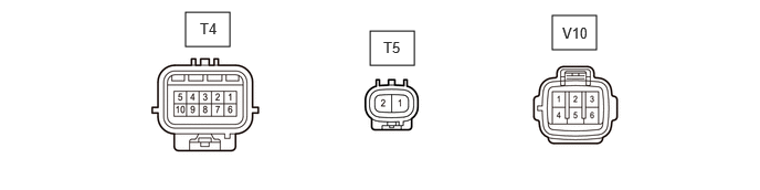
Disconnect the T4 and V10 slide door motor unit LH (slide door ECU LH) connectors.
Measure the voltage and resistance according to the value(s) in the table below.
| Tester Connection | Wiring Color | Terminal Description | Condition | Specified Condition |
|---|---|---|---|---|
| V10-3 (B) - Body ground | L - Body ground | Power supply | Always | 11 to 14 V |
| V10-2 (MSW) - Body ground | GR - Body ground | Power slide door main switch signal | Power slide door main switch on → off | Below 1 Ω → 10 kΩ or higher |
| V10-1 (GND) - Body ground | W-B - Body ground | Ground | Always | Below 1 Ω |
| V10-6 (ECUB) - Body ground | GR - Body ground | Power supply | Always | 11 to 14 V |
| T4-1 (OS) - T4-4 (OSG) | GR - W | Power slide door sensor assembly LH signal | Power slide door sensor assembly LH pushed → not pushed | Below 100 Ω → 1 kΩ or higher |
| T4-4 (OSG) - Body ground | W - Body ground | Power slide door sensor assembly LH ground | Always | Below 1 Ω |
| T4-8 (DS1) - Body ground | L - Body ground | Slide door lock remote control assembly LH (open switch) signal | Inside handle or outside handle not operated → inside handle or outside handle operated to open side | 10 kΩ or higher → Below 1 Ω |
| T4-7 (DS2) - Body ground | LG - Body ground | Slide door lock remote control assembly LH (close switch) signal | Inside handle or outside handle not operated → inside handle or outside handle operated to close side | 10 kΩ or higher → Below 1 Ω |
Reconnect the T4 and V10 slide door motor unit LH (slide door ECU LH) connectors.
Measure the voltage and resistance according to the value(s) in the table below.
| Tester Connection | Wiring Color | Terminal Description | Condition | Specified Condition |
|---|---|---|---|---|
| T4-4 (OSG) - Body ground | W - Body ground | Power slide door sensor assembly LH ground | Always | Below 1 Ω |
CHECK MAIN BODY ECU (MULTIPLEX NETWORK BODY ECU), INSTRUMENT PANEL JUNCTION BLOCK ASSEMBLY
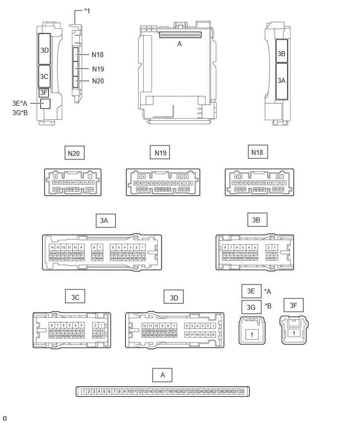
| *A | for LHD | *B | for RHD |
| *1 | Main Body ECU (Multiplex Network Body ECU) | - | - |
Remove the main body ECU (multiplex network body ECU).
Reconnect the instrument panel junction block assembly connector.
Measure the voltage and resistance according to the value(s) in the table below.
| Tester Connection | Wiring Color | Terminal Description | Condition | Specified Condition |
|---|---|---|---|---|
| A-31 (BECU) - Body ground | None - Body ground | Power supply | Always | 11 to 14 V |
| A-30 (ACC) - Body ground | None - Body ground | ACC power supply | Ignition switch off | Below 1 V |
| Ignition switch ACC | 11 to 14 V | |||
| A-32 (IG) - Body ground | None - Body ground | IG power supply | Ignition switch off | Below 1 V |
| Ignition switch ON | 11 to 14 V | |||
| A-11 (GND1) - Body ground | None - Body ground | Ground | Always | Below 1 Ω |
| N18-17 (RLSC) - Body ground | W - Body ground | No. 2 power slide door control switch (slide door close switch LH) signal | No. 2 power slide door control switch (slide door close switch LH) on → off | Below 1 Ω → 10 kΩ or higher |
| N18-27 (RRSC) - Body ground | BR - Body ground | No. 1 power slide door control switch (slide door close switch RH) signal | No. 1 power slide door control switch (slide door close switch RH) on → off | Below 1 Ω → 10 kΩ or higher |
| N18-16 (RLSD) - Body ground | B - Body ground | No. 2 power slide door control switch (slide door open switch LH) signal | No. 2 power slide door control switch (slide door open switch LH) on → off | Below 1 Ω → 10 kΩ or higher |
| N18-26 (RRSD) - Body ground | R - Body ground | No. 1 power slide door control switch (slide door open switch RH) signal | No. 1 power slide door control switch (slide door open switch RH) on → off | Below 1 Ω → 10 kΩ or higher |