METER / GAUGE / DISPLAY METER / GAUGE SYSTEM B150013 Fuel Sender Circuit Open
DESCRIPTION
| DTC No. | Detection Item | DTC Detection Condition | Trouble Area | Note |
|---|---|---|---|---|
| B150013 | Fuel Sender Circuit Open | Diagnosis Condition:
·
The ignition switch ON ·
IG power source voltage is 9.5 V or more Malfunction Status: ·
Voltage signal from fuel sender gauge assembly is 0.2 V or less ·
Voltage signal from fuel sender gauge assembly is 4.7 V or more Malfunction Time: 10 seconds or more |
·
Harness or connector ·
Fuel sender gauge assembly ·
Fuel suction tube with pump and gauge assembly*1 ·
Fuel tank vent tube assembly*2 ·
Combination meter assembly |
- |
*1: for 7GR-FKS
*2: for 1GD-FTV
WIRING DIAGRAM
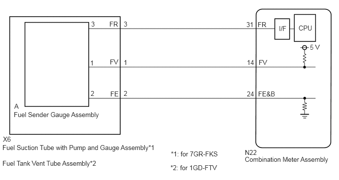
CAUTION / NOTICE / HINT
- CAUTION:
-
Be careful of flames.
- NOTICE:
-
When replacing the combination meter assembly, always replace it with a new one. If a combination meter assembly which was installed to another vehicle is used, the information stored in it will not match the information from the vehicle and a DTC may be stored.
PROCEDURE
Check vehicle condition.
- Result:
Result Proceed to for 7GR-FKS A for 1GD-FTV B
A
B
Disconnect the X6 fuel suction with pump and gauge tube assembly connector.
Disconnect the N22 combination meter assembly connector.
Measure the resistance according to the value(s) in the table below.
- Standard Resistance:
Tester Connection Condition Specified Condition X6-3 (FR) - N22-31 (FR) Always Below 1 Ω X6-2 (FE) - N22-24 (FE&B) Always Below 1 Ω X6-1 (FV) - N22-14 (FV) Always Below 1 Ω X6-3 (FR) or N22-31 (FR) - Other terminals and body ground Always 10 kΩ or higher X6-2 (FE) or N22-24 (FE&B) - Other terminals and body ground Always 10 kΩ or higher X6-1 (FV) or N22-14 (FV) - Other terminals and body ground Always 10 kΩ or higher
- Result:
Proceed to OK NG
OK
NG
Inspect the fuel sender gauge assembly.
- Result:
Proceed to OK NG
OK
NG
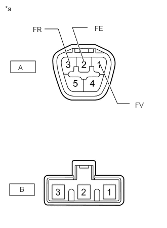
| *a | Component without harness connected
(Fuel Suction with Pump and Gauge Tube Assembly) |
Remove fuel suction with pump and gauge tube assembly.
Measure the resistance according to the value(s) in the table below.
- Standard Resistance:
Tester Connection Condition Specified Condition A-1 (FV) - B-3 Always Below 1 Ω A-2 (FE) - B-2 Always Below 1 Ω A-3 (FR) - B-1 Always Below 1 Ω
- Result:
Proceed to OK NG
OK
NG
Disconnect the X6 fuel tank vent tube assembly connector.
Disconnect the N22 combination meter assembly connector.
Measure the resistance according to the value(s) in the table below.
- Standard Resistance:
Tester Connection Condition Specified Condition X6-3 (FR) - N22-31(FR) Always Below 1 Ω X6-2 (FE) - N22-24 (FE&B) Always Below 1 Ω X6-1 (FV) - N22-14 (FV) Always Below 1 Ω X6-3 (FR) or N22-31 (FR) - Other terminals and body ground Always 10 kΩ or higher X6-2 (FE) or N22-24 (FE&B) - Other terminals and body ground Always 10 kΩ or higher X6-1 (FV) or N22-14 (FV) - Other terminals and body ground Always 10 kΩ or higher
- Result:
Proceed to OK NG
OK
NG
Inspect the fuel sender gauge assembly.
- Result:
Proceed to OK NG
OK
NG
| *a | Component without harness connected
(Fuel Tank Vent Tube Assembly) |
Measure the resistance according to the value(s) in the table below.
- Standard Resistance:
Tester Connection Condition Specified Condition A-1 (FV) - B-3 Always Below 1 Ω A-2 (FE) - B-2 Always Below 1 Ω A-3 (FR) - B-1 Always Below 1 Ω
- Result:
Proceed to OK NG
OK
NG