NAVIGATION / MULTI INFO DISPLAY NAVIGATION SYSTEM(Production Date from 2023/04) U102000 Lost Communication with Ethernet
DESCRIPTION
This DTC is stored when the radio and display receiver assembly detects a malfunction in the Ethernet network.
| DTC No. | Detection Item | DTC Detection Condition | Trouble Area | DTC Output from | Priority |
|---|---|---|---|---|---|
| U102000 | Lost Communication with Ethernet | A broken link in the Ethernet communication system is detected
(2 trip detection logic) |
·
Combination meter assembly ·
Radio and display receiver assembly |
Navigation System | A |
WIRING DIAGRAM
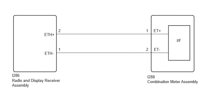
CAUTION / NOTICE / HINT
- NOTICE:
- ·
Depending on the parts that are replaced during vehicle inspection or maintenance, performing initialization, registration or calibration may be needed.
·When replacing the combination meter assembly, replace it with a new one. If a combination meter assembly which was installed to another vehicle is used, the information stored in the combination meter assembly will not match the information from the vehicle and a DTC may be stored.
·When replacing the combination meter assembly, make sure to update the ECU security key.
- HINT:
- ·
Before disconnecting the connectors for inspection, push each connector in the connection direction and check that it is not lose or disconnected.
·After disconnecting the connector, check that the connector and terminals are not damaged, deformed or corroded.
PROCEDURE
Pre-procedure1
Disconnect the I286 radio and display receiver assembly connector.
Disconnect the I288 combination meter assembly connector.
Procedure1
Measure the resistance according to the value(s) in the table below.
- Standard Resistance:
Tester Connection Condition Specified Condition I286-2 (ETH+) - I288-1 (ET+) Always Below 1 Ω I286-1 (ETH-) - I288-2 (ET-) Always Below 1 Ω I286-2 (ETH+) - Body ground Always 10 kΩ or higher I286-1 (ETH-) - Body ground Always 10 kΩ or higher
- Result:
Proceed to OK NG
Post-procedure1
None
OK
NG
Replace the combination meter assembly with a new one.
- Result:
Proceed to NEXT
NEXT
Clear the DTCs.
- Body Electrical > Navigation System > Clear DTCs
- 50002 496
- Result:
Proceed to NEXT
NEXT
Pre-procedure1
Turn the ignition switch off.
Turn the ignition switch to ON and wait for 45 seconds.
Turn the ignition switch off.
Turn the ignition switch to ON and wait for 45 seconds.
Procedure1
Check for DTCs and proceed to the following step.
- Body Electrical > Navigation System > Trouble Codes
- 50001 496
- Result:
Result Proceed to DTCs are not output A DTC U102000 is output B
Post-procedure1
None
A
B