LIGHTING (EXT) LIGHTING SYSTEM B124400 Light Sensor Circuit Malfunction
DESCRIPTION
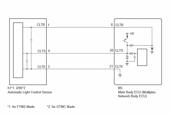
The automatic light control sensor detects ambient light. The sensor creates an electrical signal based on the amount of light detected, and sends the signal to the main body ECU (multiplex network body ECU). The main body ECU (multiplex network body ECU) turns on or off the headlights and taillights according to the signal.
| DTC No. | Detection Item | DTC Detection Condition | Trouble Area |
|---|---|---|---|
| B124400 | Light Sensor Circuit Malfunction | Detection condition:
The ignition switch is to ON. Malfunction status:
Either of the following conditions is met: -
Malfunction in automatic light control sensor -
Open or short in automatic light control sensor circuit Malfunction duration:
5 seconds or more |
·
Automatic light control sensor ·
Harness or connector ·
Main body ECU (multiplex network body ECU) |
WIRING DIAGRAM
CAUTION / NOTICE / HINT
- NOTICE:
-
Before replacing the main body ECU (multiplex network body ECU), refer to Service Bulletin.*1
*1: w/ Smart Entry and Start System
PROCEDURE
Clear the DTCs.
- Body Electrical > Main Body > Clear DTCs
- 50002 449
- Result:
Proceed to NEXT
NEXT
Turn the ignition switch to ON.
Wait 10 seconds or more.
Check for DTCs.
- Body Electrical > Main Body > Trouble Codes
- 50001 449
- Result:
Result Proceed to B124400 is not output A B124400 is output B
A
B
Cover the automatic light control sensor with an opaque object.
According to the display on the GTS, read the Data List and check that the value of Light Sensor Illuminance changes while performing the following:
Slowly move the opaque object to uncover and then cover the automatic light control sensor.
- Body Electrical > Main Body > Data List
-
Tester Display Measurement Item Normal Condition Reference Value Diagnostic Note Light Sensor Illuminance Light control sensor illuminance 0 to 8191 lx or Sensor Fail Value is output according to ambient light level The displayed value is "0" when no light is detected.
- Body Electrical > Main Body > Data List
-
Tester Display Light Sensor Illuminance - 50003 449 113
- OK:
The value changes according to the amount the automatic light control sensor is covered.
- Result:
Proceed to OK NG
OK
NG
Disconnect the h1*1 or I290*2 automatic light control sensor connector.
*1: for FTMS Made
*2: for GTMC Made
Disconnect the I85 main body ECU (multiplex network body ECU) connector.
Measure the resistance according to the value(s) in the table below.
- Standard Resistance:
for FTMS Made: Tester Connection Condition Specified Condition h1-1 (CLTB) - I85-8 (CLTB) Always Below 1 Ω h1-4 (CLTS) - I85-20 (CLTS) Always Below 1 Ω h1-2 (CLTE) - I85-21 (CLTE) Always Below 1 Ω h1-1 (CLTB) - Body ground Always 10 kΩ or higher I85-8 (CLTB) - Body ground Always 10 kΩ or higher h1-4 (CLTS) - Body ground Always 10 kΩ or higher I85-20 (CLTS) - Body ground Always 10 kΩ or higher h1-2 (CLTE) - Body ground Always 10 kΩ or higher I85-21 (CLTE) - Body ground Always 10 kΩ or higher
for GTMC Made: Tester Connection Condition Specified Condition I290-1 (CLTB) - I85-8 (CLTB) Always Below 1 Ω I290-4 (CLTS) - I85-20 (CLTS) Always Below 1 Ω I290-2 (CLTE) - I85-21 (CLTE) Always Below 1 Ω I290-1 (CLTB) - Body ground Always 10 kΩ or higher I85-8 (CLTB) - Body ground Always 10 kΩ or higher I290-4 (CLTS) - Body ground Always 10 kΩ or higher I85-20 (CLTS) - Body ground Always 10 kΩ or higher I290-2 (CLTE) - Body ground Always 10 kΩ or higher I85-21 (CLTE) - Body ground Always 10 kΩ or higher
- Result:
Proceed to OK NG
OK
NG
Connect the I85 main body ECU (multiplex network body ECU) connector.
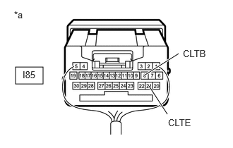
| *a | Component with harness connected
(Main Body ECU (Multiplex Network Body ECU)) |
Measure the voltage according to the value(s) in the table below.
- Standard Voltage:
Tester Connection Switch Condition Specified Condition I85-8 (CLTB) - I85-21 (CLTE) Ignition switch off Below 1 V I85-8 (CLTB) - I85-21 (CLTE) Ignition switch ON 11 to 14 V
- Result:
Proceed to OK NG
OK
NG
- Result:
Proceed to OK NG
OK
NG