RM38T0EC _58 Vehicle Interior _115230 THEFT DETERRENT / KEYLESS ENTRY _0512196 THEFT DETERRENT SYSTEM J

THEFT DETERRENT / KEYLESS ENTRY  THEFT DETERRENT SYSTEM  Security Horn Circuit  


DESCRIPTION

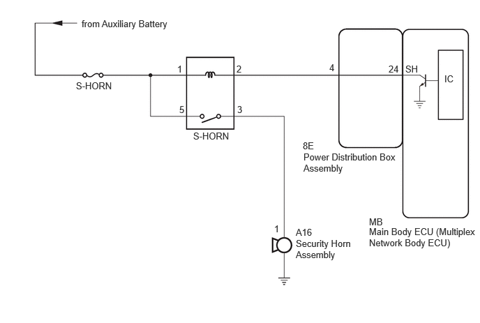
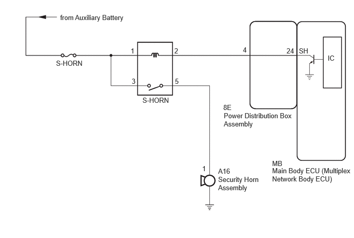
When the theft deterrent system is switched from the armed state to the alarm sounding state, the main body ECU (multiplex network body ECU) transmits a signal to cause the security horn assembly to sound at intervals of 0.4 seconds.

WIRING DIAGRAM

Production Date from 2022/01 to 2023/04


B591723E32
1.219,0.271 3.365,0.469 2.146,0.198 10 false from Auxiliary Battery 1.135,1.198 2.385,1.396 1.25,0.198 10 false S-HORN 2.885,1.948 4.135,2.146 1.25,0.198 10 false S-HORN 4.531,2.26 5.969,3.021 1.438,0.76 10 false Power Distribution Box Assembly 4.417,3.385 4.906,3.604 0.49,0.219 10 false A16 4.417,3.552 5.26,4.01 0.844,0.458 10 false Security Horn Assembly 5.51,3.229 6,3.448 0.49,0.219 10 false MB 5.51,3.375 7.135,3.771 1.625,0.396 10 false Main Body ECU (Multiplex Network Body ECU) 4.521,2.094 5.01,2.313 0.49,0.219 10 false 8E 4.917,0.927 5.406,1.146 0.49,0.219 10 false 4 5.802,0.948 6.292,1.167 0.49,0.219 10 false 24 6.052,0.948 6.542,1.167 0.49,0.219 10 false SH 6.635,1.094 6.885,1.333 0.25,0.24 10 false IC 2.646,0.948 2.979,1.156 0.333,0.208 10 false 1 2.667,1.563 3.042,2 0.375,0.438 10 false 3 3.531,0.948 3.865,1.156 0.333,0.208 10 false 2 3.542,1.563 3.885,1.948 0.344,0.385 10 false 5 4.094,3.333 4.427,3.542 0.333,0.208 10 false 1

Production Date from 2023/04


B591723E31
1.219,0.271 3.365,0.469 2.146,0.198 10 false from Auxiliary Battery 1.135,1.198 2.385,1.396 1.25,0.198 10 false S-HORN 2.885,1.948 4.135,2.146 1.25,0.198 10 false S-HORN 4.531,2.26 5.969,3.021 1.438,0.76 10 false Power Distribution Box Assembly 4.417,3.385 4.906,3.604 0.49,0.219 10 false A16 4.417,3.552 5.26,4.01 0.844,0.458 10 false Security Horn Assembly 5.51,3.229 6,3.448 0.49,0.219 10 false MB 5.51,3.375 7.135,3.771 1.625,0.396 10 false Main Body ECU (Multiplex Network Body ECU) 4.521,2.094 5.01,2.313 0.49,0.219 10 false 8E 4.917,0.927 5.406,1.146 0.49,0.219 10 false 4 5.802,0.948 6.292,1.167 0.49,0.219 10 false 24 6.052,0.948 6.542,1.167 0.49,0.219 10 false SH 6.635,1.094 6.885,1.333 0.25,0.24 10 false IC 2.646,0.948 2.979,1.156 0.333,0.208 10 false 1 2.677,1.552 3.052,1.99 0.375,0.438 10 false 5 3.531,0.948 3.865,1.156 0.333,0.208 10 false 2 3.542,1.552 3.885,1.938 0.344,0.385 10 false 3 4.094,3.333 4.427,3.542 0.333,0.208 10 false 1

CAUTION / NOTICE / HINT

NOTICE:
·

Before replacing the main body ECU (multiplex network body ECU), refer to Service Bulletin.

·

Inspect the fuses for circuits related to this system before performing the following procedure.


PROCEDURE

1.CONFIRM MODEL
a.

Choose the model to be inspected.


Result:
Result Proceed to
Production date from 2022/01 to 2023/04 A
Production date from 2023/04 B


A

2.PERFORM ACTIVE TEST USING GTS

B

9.PERFORM ACTIVE TEST USING GTS
2.PERFORM ACTIVE TEST USING GTS
a.

Perform the Active Test according to the display on the GTS.

Body Electrical > Main Body > Active Test
Tester Display Measurement Item Control Range Diagnostic Note
Security Horn Security horn Assembly OFF/ON -
Body Electrical > Main Body > Active Test
Tester Display
Security Horn
50004 449 3
OK:

The security horn assembly sounds and stops correctly when operated through the GTS.


Result:
Proceed to
OK
NG


OK

NG

3.INSPECT SECURITY HORN ASSEMBLY
4.INSPECT S-HORN RELAY
a.
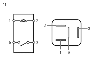
B256934C26
2.188,1.469 2.188,1.802 true 2.833,1.042 3.167,1.042 true 2.479,1.354 2.479,1.823 true 1.698,0.927 2.031,0.927 true 0.104,0.083 0.417,0.396 0.313,0.313 10 false *1 0.323,1.458 0.573,1.75 0.25,0.292 10 false 5 1.313,0.667 1.594,0.917 0.281,0.25 10 false 2 0.313,0.667 0.51,0.906 0.198,0.24 10 false 1 1.313,1.469 1.563,1.708 0.25,0.24 10 false 3 2.469,1.833 2.688,2.052 0.219,0.219 10 false 5 2.146,1.833 2.375,2.063 0.229,0.229 10 false 1 1.583,0.844 1.875,1.115 0.292,0.271 10 false 2 3.188,0.958 3.333,1.188 0.146,0.229 10 false 3
*1 S-HORN Relay


Remove the S-HORN relay from the No. 1 engine room relay block.


b.

Measure the resistance according to the value(s) in the table below.

Standard Resistance:
Tester Connection Condition Specified Condition
3 - 5 Auxiliary battery voltage not applied between terminals 1 and 2 10 kΩ or higher
3 - 5 Auxiliary battery voltage applied between terminals 1 and 2 Below 1 Ω


Result:
Proceed to
OK
NG


OK

5.INSPECT POWER DISTRIBUTION BOX ASSEMBLY

NG

REPLACE S-HORN RELAY

5.INSPECT POWER DISTRIBUTION BOX ASSEMBLY
a.

Remove the main body ECU (multiplex network body ECU).
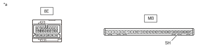
Click herePower Source / Network>POWER DISTRIBUTION>MAIN BODY ECU>REMOVAL

B591722C03
1.354,0.25 1.771,0.5 0.417,0.25 4.813,0.5 5.229,0.75 0.417,0.25 5.719,1.375 5.99,1.094 true 0.115,0.063 0.427,0.219 0.313,0.156 10 false *a 1.469,0.292 1.781,0.49 0.313,0.198 10 false 8E 4.927,0.531 5.24,0.729 0.313,0.198 10 false MB 5.5,1.365 6.063,1.583 0.563,0.219 10 false SH
*a Component without harness connected
(Power Distribution Box Assembly)
- -


b.

Disconnect the 8E power distribution box assembly connector.


c.

Measure the resistance according to the value(s) in the table below.

Standard Resistance:
Tester Connection Condition Specified Condition
8E-4 - MB-24 (SH) Always Below 1 Ω


Result:
Proceed to
OK
NG


OK

6.CHECK HARNESS AND CONNECTOR (AUXILIARY BATTERY - S-HORN RELAY)

NG

6.CHECK HARNESS AND CONNECTOR (AUXILIARY BATTERY - S-HORN RELAY)
a.
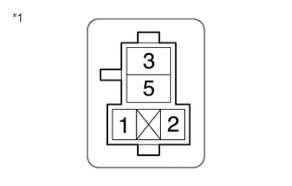
B340809C03
0.146,0.125 0.458,0.281 0.313,0.156 10 false *1
*1 No. 1 Engine Room Relay Block


Measure the voltage according to the value(s) in the table below.

Standard Voltage:
Tester Connection Switch Condition Specified Condition
S-HORN relay holder terminal 1 - Body ground Ignition switch off 11 to 14 V
S-HORN relay holder terminal 3 - Body ground*1 Ignition switch off 11 to 14 V


Result:
Proceed to
OK
NG


OK

7.CHECK HARNESS AND CONNECTOR (S-HORN RELAY - SECURITY HORN ASSEMBLY)

NG

REPAIR OR REPLACE HARNESS OR CONNECTOR

7.CHECK HARNESS AND CONNECTOR (S-HORN RELAY - SECURITY HORN ASSEMBLY)
a.
B340809C03
0.146,0.125 0.458,0.281 0.313,0.156 10 false *1
*1 No. 1 Engine Room Relay Block


Measure the resistance according to the value(s) in the table below.

Standard Resistance:
Tester Connection Condition Specified Condition
S-HORN relay holder terminal 5 - A16-1 Always Below 1 Ω
S-HORN relay holder terminal 5 or A16-1 - Other terminals and body ground Always 10 kΩ or higher


Result:
Proceed to
OK
NG


OK

8.CHECK HARNESS AND CONNECTOR (S-HORN RELAY - POWER DISTRIBUTION BOX ASSEMBLY)

NG

REPAIR OR REPLACE HARNESS OR CONNECTOR

8.CHECK HARNESS AND CONNECTOR (S-HORN RELAY - POWER DISTRIBUTION BOX ASSEMBLY)
a.
B340809C03
0.146,0.125 0.458,0.281 0.313,0.156 10 false *1
*1 No. 1 Engine Room Relay Block


Measure the resistance according to the value(s) in the table below.

Standard Resistance:
Tester Connection Condition Specified Condition
S-HORN relay holder terminal 2 - 8E-4 Always Below 1 Ω
S-HORN relay holder terminal 2 or 8E-4 - Other terminals and body ground Always 10 kΩ or higher


Result:
Proceed to
OK
NG


OK

NG

REPAIR OR REPLACE HARNESS OR CONNECTOR

9.PERFORM ACTIVE TEST USING GTS
a.

Perform the Active Test according to the display on the GTS.

Body Electrical > Main Body > Active Test
Tester Display Measurement Item Control Range Diagnostic Note
Security Horn Security horn Assembly OFF/ON -
Body Electrical > Main Body > Active Test
Tester Display
Security Horn
50004 449 3
OK:

The security horn assembly sounds and stops correctly when operated through the GTS.


Result:
Proceed to
OK
NG


OK

NG

10.INSPECT SECURITY HORN ASSEMBLY
11.INSPECT S-HORN RELAY
a.
B256934C26
2.188,1.469 2.188,1.802 true 2.833,1.042 3.167,1.042 true 2.479,1.354 2.479,1.823 true 1.698,0.927 2.031,0.927 true 0.104,0.083 0.417,0.396 0.313,0.313 10 false *1 0.323,1.458 0.573,1.75 0.25,0.292 10 false 5 1.313,0.667 1.594,0.917 0.281,0.25 10 false 2 0.313,0.667 0.51,0.906 0.198,0.24 10 false 1 1.313,1.469 1.563,1.708 0.25,0.24 10 false 3 2.469,1.833 2.688,2.052 0.219,0.219 10 false 5 2.146,1.833 2.375,2.063 0.229,0.229 10 false 1 1.583,0.844 1.875,1.115 0.292,0.271 10 false 2 3.188,0.958 3.333,1.188 0.146,0.229 10 false 3
*1 S-HORN Relay


Remove the S-HORN relay from the No. 1 engine room relay block.


b.

Measure the resistance according to the value(s) in the table below.

Standard Resistance:
Tester Connection Condition Specified Condition
3 - 5 Auxiliary battery voltage not applied between terminals 1 and 2 10 kΩ or higher
3 - 5 Auxiliary battery voltage applied between terminals 1 and 2 Below 1 Ω


Result:
Proceed to
OK
NG


OK

12.INSPECT POWER DISTRIBUTION BOX ASSEMBLY

NG

REPLACE S-HORN RELAY

12.INSPECT POWER DISTRIBUTION BOX ASSEMBLY
a.

Remove the main body ECU (multiplex network body ECU).

Click herePower Source / Network>POWER DISTRIBUTION>MAIN BODY ECU>REMOVAL

B591722C03
1.354,0.25 1.771,0.5 0.417,0.25 4.813,0.5 5.229,0.75 0.417,0.25 5.719,1.375 5.99,1.094 true 0.115,0.063 0.427,0.219 0.313,0.156 10 false *a 1.469,0.292 1.781,0.49 0.313,0.198 10 false 8E 4.927,0.531 5.24,0.729 0.313,0.198 10 false MB 5.5,1.365 6.063,1.583 0.563,0.219 10 false SH
*a Component without harness connected
(Power Distribution Box Assembly)
- -


b.

Disconnect the 8E power distribution box assembly connector.


c.

Measure the resistance according to the value(s) in the table below.

Standard Resistance:
Tester Connection Condition Specified Condition
8E-4 - MB-24 (SH) Always Below 1 Ω


Result:
Proceed to
OK
NG


OK

13.CHECK HARNESS AND CONNECTOR (AUXILIARY BATTERY - S-HORN RELAY)

NG

13.CHECK HARNESS AND CONNECTOR (AUXILIARY BATTERY - S-HORN RELAY)
a.
B340809C03
0.146,0.125 0.458,0.281 0.313,0.156 10 false *1
*1 No. 1 Engine Room Relay Block


Measure the voltage according to the value(s) in the table below.

Standard Voltage:
Tester Connection Switch Condition Specified Condition
S-HORN relay holder terminal 1 - Body ground Ignition switch off 11 to 14 V
S-HORN relay holder terminal 5 - Body ground Ignition switch off 11 to 14 V


Result:
Proceed to
OK
NG


OK

14.CHECK HARNESS AND CONNECTOR (S-HORN RELAY - SECURITY HORN ASSEMBLY)

NG

REPAIR OR REPLACE HARNESS OR CONNECTOR

14.CHECK HARNESS AND CONNECTOR (S-HORN RELAY - SECURITY HORN ASSEMBLY)
a.
B340809C03
0.146,0.125 0.458,0.281 0.313,0.156 10 false *1
*1 No. 1 Engine Room Relay Block


Measure the resistance according to the value(s) in the table below.

Standard Resistance:
Tester Connection Condition Specified Condition
S-HORN relay holder terminal 3 - A16-1 Always Below 1 Ω
S-HORN relay holder terminal 3 or A16-1 - Other terminals and body ground Always 10 kΩ or higher


Result:
Proceed to
OK
NG


OK

15.CHECK HARNESS AND CONNECTOR (S-HORN RELAY - POWER DISTRIBUTION BOX ASSEMBLY)

NG

REPAIR OR REPLACE HARNESS OR CONNECTOR

15.CHECK HARNESS AND CONNECTOR (S-HORN RELAY - POWER DISTRIBUTION BOX ASSEMBLY)
a.
B340809C03
0.146,0.125 0.458,0.281 0.313,0.156 10 false *1
*1 No. 1 Engine Room Relay Block


Measure the resistance according to the value(s) in the table below.

Standard Resistance:
Tester Connection Condition Specified Condition
S-HORN relay holder terminal 2 - 8E-4 Always Below 1 Ω
S-HORN relay holder terminal 2 or 8E-4 - Other terminals and body ground Always 10 kΩ or higher


Result:
Proceed to
OK
NG


OK

NG

REPAIR OR REPLACE HARNESS OR CONNECTOR