BRAKE CONTROL / DYNAMIC CONTROL SYSTEMS ELECTRONICALLY CONTROLLED BRAKE SYSTEM(for HEV Model) VSC OFF Switch Circuit
DESCRIPTION
The skid control ECU (brake actuator assembly) is connected to the combination meter assembly via CAN communication.
Pressing the VSC OFF switch turns off TRC operation, and pressing and holding this switch turns off TRC and VSC operation. If TRC and VSC operations are turned off, "Traction Control Turned Off" will be displayed on the multi-information display and the VSC OFF indicator light will come on.
WIRING DIAGRAM
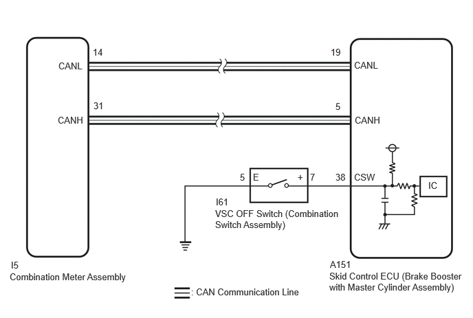
PROCEDURE
Operate the GTS to read the Data List.
- Chassis > Brake/EPB > Data List
-
Tester Display Measurement Item Range Normal Condition Diagnostic Note TRC(TRAC)/VSC OFF Mode TRC/VSC off mode Normal mode (TRC(TRAC) ON/VSC ON) /
TRC(TRAC) OFF mode (TRC(TRAC) OFF/VSC ON) /
VSC expert mode (VSC expert mode MID ON) /
VSC OFF mode (TRC(TRAC) OFF/VSC OFF)Normal mode (TRC(TRAC) ON/VSC ON): Normal mode
TRC(TRAC) OFF mode (TRC(TRAC) OFF/VSC ON): TRC off mode
VSC expert mode (VSC expert mode MID ON): VSC expert mode
VSC OFF mode (TRC(TRAC) OFF/VSC OFF): VSC off mode-
- Chassis > Brake/EPB > Data List
-
Tester Display TRC(TRAC)/VSC OFF Mode - 50003 435 45
Check the indicator light and mode condition on the GTS changes according to VSC OFF switch operation.
- Standard:
Switch Operation Mode Condition Display Multi-information Display ("Traction Control Turned Off") VSC OFF Indicator Light Not pressed Normal mode (TRC(TRAC) ON/VSC ON) Not displayed Does not come on Pressing the VSC OFF switch TRC(TRAC) OFF mode (TRC(TRAC) OFF/VSC ON) Displayed Does not come on Pressing and holding the VSC OFF switch VSC OFF mode (TRC(TRAC) OFF/VSC OFF) Displayed Comes on
- Result:
Result Proceed to Indicator light and mode condition display do not change (VSC OFF switch (for Console Box)) A Mode condition display is normal, but indicator light does not change B Indicator light and mode condition display are normal C
A
B
C
- OK:
The VSC OFF switch (combination switch assembly) is normal.
- Result:
Proceed to OK NG
OK
NG
Make sure that there is no looseness at the locking part and the connecting part of the connector.
- OK:
The connector is securely connected.
Disconnect the A151 skid control ECU (brake actuator assembly) connector.
Disconnect the I61 VSC OFF switch (combination switch assembly) connector.
Check both the connector case and the terminals for deformation and corrosion.
- OK:
No deformation or corrosion.
Measure the resistance according to the value(s) in the table below.
- Standard Resistance:
Tester Connection Condition Specified Condition I61-7 (+) - A151-38 (CSW) Always Below 1 Ω I61-7 (+) or A151-38 (CSW) - Body ground Always 10 kΩ or higher I61-5 (E) - Body ground 1 minute or more after disconnecting the cable from the negative (-) auxiliary battery terminal Below 1 Ω
- Result:
Proceed to OK NG
OK
NG