BRAKE CONTROL / DYNAMIC CONTROL SYSTEMS ELECTRONICALLY CONTROLLED BRAKE SYSTEM(for HEV Model) C051212 Right Rear Wheel Speed Sensor Circuit Short to Battery
DESCRIPTION
Each speed sensor detects wheel speed and sends signals to the skid control ECU (brake actuator assembly). These signals are used by the brake control.
The speed sensor detects the magnetic fields of the speed sensor rotor as it rotates and outputs a pulse signal.
The frequency of the pulse varies in accordance with the rotational speed of the speed sensor rotor and the system uses this to determine the wheel speed.
| DTC No. | Detection Item | DTC Detection Condition | Trouble Area | MIL | DTC Output from | Note |
|---|---|---|---|---|---|---|
| C051212 | Right Rear Wheel Speed Sensor Circuit Short to Battery | A short to +B in the speed sensor signal circuit is detected for 0.12 seconds or more. | ·
Rear speed sensor RH (rear axle hub and bearing assembly RH) ·
Wire harness or connector ·
Skid control sensor wire RH (No. 1 parking brake wire assembly) ·
Skid control ECU (brake actuator assembly) |
Comes on | Brake/EPB | ·
SAE Code: C0515 (Case 1) ·
Output ECU: Skid control ECU (brake actuator assembly) |
CONFIRMATION DRIVING PATTERN
- NOTICE:
-
When performing the normal judgment procedure, make sure that the driver door is closed and is not opened at any time during the procedure.
- HINT:
- ·
After repair has been completed, clear the DTC and then check that the vehicle has returned to normal by performing the following All Readiness check procedure.
·When clearing the permanent DTCs, refer to the "CLEAR PERMANENT DTC" procedure.
Connect the GTS to the DLC3.
Turn the ignition switch to ON and turn the GTS on.
Clear the DTCs (even if no DTCs are stored, perform the clear DTC procedure).
Turn the ignition switch off.
Turn the ignition switch to ON (READY) and turn the GTS on.
Wait for 1 second or more. [*]
- HINT:
-
[*]: Normal judgment procedure.
-
The normal judgment procedure is used to complete DTC judgment and also used when clearing permanent DTCs.
Enter the following menus: Chassis / Brake/EPB* / Utility / All Readiness.
*: Electric Parking Brake System
Check the DTC judgment result.
- HINT:
- ·
If the judgment result shows NORMAL, the system is normal.
·If the judgment result shows ABNORMAL, the system has a malfunction.
·If the judgment result shows INCOMPLETE, perform driving pattern again.
WIRING DIAGRAM
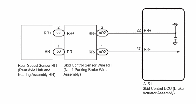
PROCEDURE
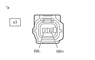
| *a | Front view of skid control sensor wire RH (No. 1 parking brake wire assembly)
(to Rear Speed Sensor RH (Rear Axle Hub and Bearing Assembly RH)) |
Make sure that there is no looseness at the locking part and the connecting part of the connectors.
- OK:
The connector is securely connected.
Disconnect the o3 rear speed sensor RH (rear axle hub and bearing assembly RH) connector.
Check both the connector case and the terminals for deformation and corrosion.
- OK:
No deformation or corrosion.
Turn the ignition switch to ON.
Measure the voltage according to the value(s) in the table below.
- Standard Voltage:
Tester Connection Condition Specified Condition o3-2 (RR+) - o3-1 (RR-) Ignition switch ON 11 to 14 V
- Result:
Proceed to OK NG
OK
NG
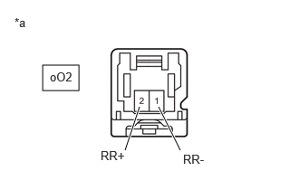
| *a | Front view of wire harness connector
(to Skid Control Sensor Wire RH (No. 1 Parking Brake Wire Assembly)) |
Make sure that there is no looseness at the locking part and the connecting part of the connectors.
- OK:
The connector is securely connected.
Disconnect the oO2 skid control sensor wire RH (No. 1 parking brake wire assembly) connector.
Check both the connector case and the terminals for deformation and corrosion.
- OK:
No deformation or corrosion.
Turn the ignition switch to ON.
Measure the voltage according to the value(s) in the table below.
- Standard Voltage:
Tester Connection Condition Specified Condition oO2-2 (RR+) - oO2-1 (RR-) Ignition switch ON 11 to 14 V
- Result:
Proceed to OK NG
OK
NG
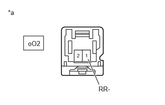
| *a | Front view of wire harness connector
(to Skid Control Sensor Wire RH (No. 1 Parking Brake Wire Assembly)) |
Make sure that there is no looseness at the locking part and the connecting part of the connectors.
- OK:
The connector is securely connected.
Disconnect the A151 skid control ECU (brake actuator assembly) connector.
Disconnect the oO2 skid control sensor wire RH (No. 1 parking brake wire assembly) connector.
Check both the connector case and the terminals for deformation and corrosion.
- OK:
No deformation or corrosion.
Measure the voltage according to the value(s) in the table below.
- Standard Voltage:
Tester Connection Condition Specified Condition oO2-1 (RR-) - Body ground Always Below 1.5 V
- Result:
Proceed to OK NG
OK
NG
Make sure that there is no looseness at the locking part and the connecting part of the connectors.
- OK:
The connector is securely connected.
Disconnect the A151 skid control ECU (brake actuator assembly) connector.
Disconnect the oO2 skid control sensor wire RH (No. 1 parking brake wire assembly) connector.
Check both the connector case and the terminals for deformation and corrosion.
- OK:
No deformation or corrosion.
Measure the resistance according to the value(s) in the table below.
- Standard Resistance:
Tester Connection Condition Specified Condition oO2-2 (RR+) or A151-22 (RR+) - oO2-1 (RR-) or A151-37 (RR-) Always 10 kΩ or higher
- Result:
Proceed to OK NG
OK
NG