REAR SUSPENSION REAR COIL SPRING INSTALLATION
CAUTION / NOTICE / HINT
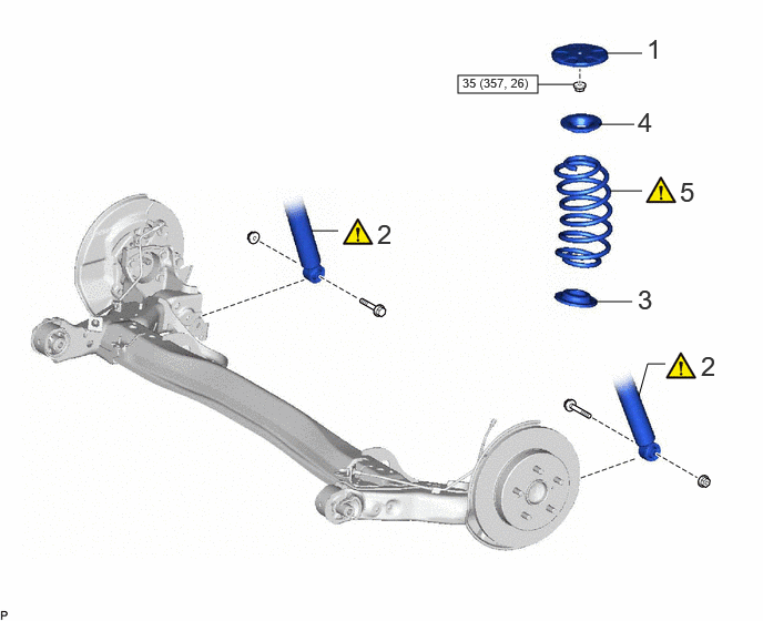
| Procedure | Part Name Code | 
|

|

|
|
|---|---|---|---|---|---|
| 1 | REAR SPRING SEAT SUB-ASSEMBLY | 42011 | - | - | - |
| 2 | SEPARATE REAR SHOCK ABSORBER ASSEMBLY | - | ( 202307,999999,_53,_112967,_0502999,RM100000002C3A9_01_0058,) 202307,999999,_53,_112967,_0502999,RM100000002C3A9_01_0058,)
|
- | - |
| 3 | REAR LOWER COIL SPRING INSULATOR | 48258C | - | - | - |
| 4 | REAR UPPER COIL SPRING INSULATOR | 48259A | - | - | - |
| 5 | REAR COIL SPRING | 48231B | (202307,999999,_53,_112967,_0502999,RM100000002C3A9_01_0053,)
|
- | - |

|
N*m (kgf*cm, ft.*lbf): Specified torque | - | - |
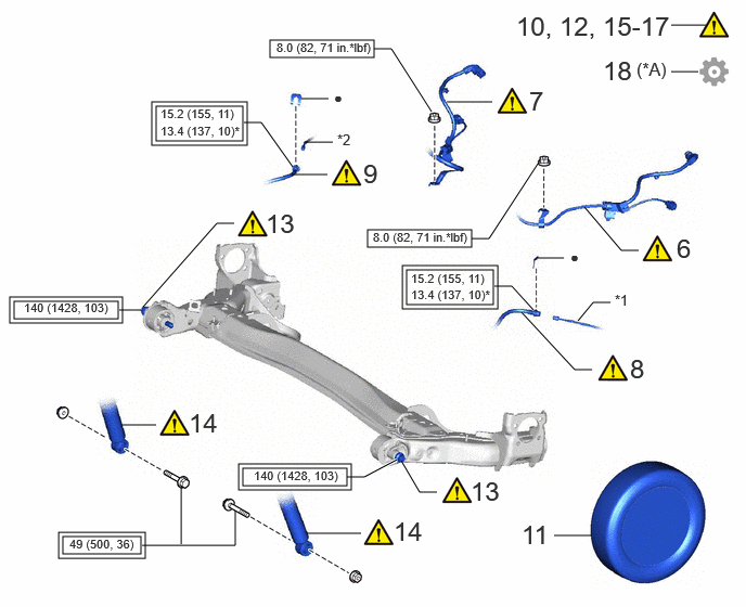
| *A | w/ Panoramic view monitor system | - | - |
| *1 | REAR NO. 4 BRAKE TUBE | *2 | REAR NO. 3 BRAKE TUBE |

|
Tightening torque for "Major areas involving basic vehicle performance such as moving/turning/stopping" : N*m (kgf*cm, ft.*lbf) |
|
N*m (kgf*cm, ft.*lbf): Specified torque |
| * | For use with a union nut wrench | ● | Non-reusable part |
CAUTION / NOTICE / HINT
- HINT:
- ·
Use the same procedure for the RH side and LH side.
·The procedure listed below is for the LH side.
PROCEDURE

 42011
1.INSTALL REAR SPRING SEAT SUB-ASSEMBLY
42011
1.INSTALL REAR SPRING SEAT SUB-ASSEMBLY
|
|
|
- Torque:
- 35 N*m (357 kgf*cm, 26 ft.*lbf)
2.SEPARATE REAR SHOCK ABSORBER ASSEMBLY
48258C
3.INSTALL REAR LOWER COIL SPRING INSULATOR
48259A
4.INSTALL REAR UPPER COIL SPRING INSULATOR
48231B
5.INSTALL REAR COIL SPRING
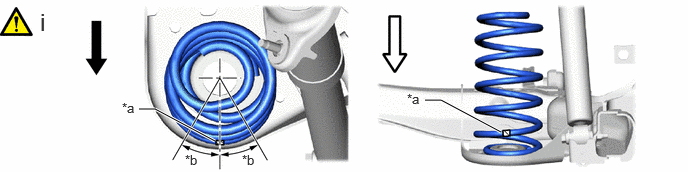
| *a | Identification Mark | *b | 30° |

|
Rear of the Vehicle | 
|
Lower of the Vehicle |
Set the rear coil spring to the rear axle beam assembly as shown in the illustration.
- NOTICE:
-
Make sure that the identification mark is positioned on the lower side of the vehicle.
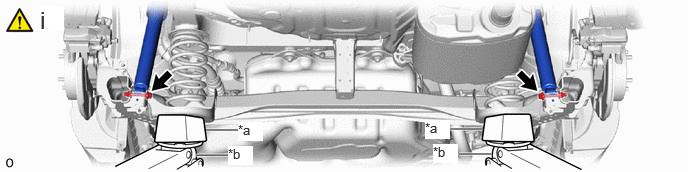
| *a | Wooden Block | *b | Jack |
Slowly jack up the rear axle beam assembly using 2 jacks and 2 wooden blocks and temporarily install the rear axle beam assembly and rear coil spring with the 2 bolts and 2 nuts.
- NOTICE:
-
Because the nuts have their own stoppers, do not turn the nuts. Tighten the bolts with the nuts secured.
890C0A
6.INSTALL NO. 2 PARKING BRAKE WIRE ASSEMBLY
|
|
|
- Torque:
- 8.0 N*m (82 kgf*cm, 71 in.*lbf)
890C0
7.INSTALL NO. 1 PARKING BRAKE WIRE ASSEMBLY
8.CONNECT REAR BRAKE TUBE FLEXIBLE HOSE LH
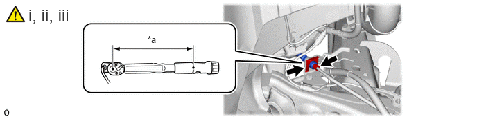
| *a | Torque Wrench Fulcrum Length | - | - |
Temporarily install the rear brake tube flexible hose LH to the rear No. 4 brake tube.
Secure the rear brake tube flexible hose LH with a new clip.
- NOTICE:
-
Install the clip as far as it will go.
Using a union nut wrench, connect the rear brake tube flexible hose LH to the rear No. 4 brake tube while holding the rear brake tube flexible hose with a wrench.
- Torque:
- Specified tightening torque : 15.2 N*m (155 kgf*cm, 11 ft.*lbf)
- NOTICE:
- ·
Do not kink or damage the brake line.
·Do not allow any foreign matter such as dirt or dust to enter the brake line from the connecting parts.
- HINT:
- ·
Calculate the torque wrench reading when changing the fulcrum length of the torque wrench.
·When using a union nut wrench (fulcrum length of 22 mm (0.866 in.)) + torque wrench (fulcrum length of 162 mm (6.38 in.)):
13.4 N*m (137 kgf*cm, 10 ft.*lbf)
9.CONNECT REAR BRAKE TUBE FLEXIBLE HOSE RH
10.BLEED BRAKE LINE
for Gasoline Model:
11.INSTALL REAR WHEELS
12.STABILIZE SUSPENSION
42110F
13.INSTALL REAR AXLE BEAM ASSEMBLY
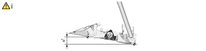
| *a | 70 mm (2.76 in.) | - | - |
Install the rear axle beam assembly as shown in the illustration.
- Torque:
- 140 N*m (1428 kgf*cm, 103 ft.*lbf)
14.INSTALL REAR SHOCK ABSORBER ASSEMBLY
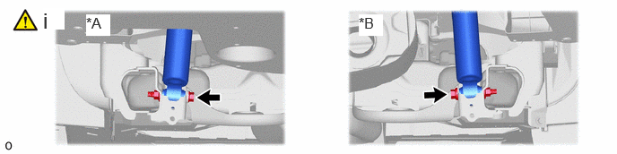
| *A | for LH Side | *B | for RH Side |
Install the rear axle beam assembly to the rear shock absorber assemblies LH and RH with the 2 bolts.
- Torque:
- 49 N*m (500 kgf*cm, 36 ft.*lbf)
- NOTICE:
-
Because the nuts have their own stoppers, do not turn the nuts. Tighten the bolts with the nuts secured.
15.CHECK FOR SPEED SENSOR SIGNAL
16.INSPECT REAR WHEEL ALIGNMENT
17. PLACE FRONT WHEELS FACING STRAIGHT AHEAD