HEATING / AIR CONDITIONING AIR CONDITIONING SYSTEM(for HEV Model) B149887 A/C Inverter Local Missing Message
DESCRIPTION
The hybrid vehicle control ECU and compressor with motor assembly communicate via direct line. Compressor control is stopped and this DTC is stored if communication information is cut off or abnormal information is received.
This DTC is also detected if high-voltage electricity supplied from the inverter with converter assembly to the compressor control circuit is shut off.
This DTC will be stored as a history DTC.
| DTC No. | Detection Item | DTC Detection Condition | Trouble Area | Memory |
|---|---|---|---|---|
| B149887 | A/C Inverter Local Missing Message | Diagnosis Condition:
READY ON Malfunction Status: ·
Error or open in communication line between the hybrid vehicle control ECU and compressor with motor assembly ·
High-voltage power source shut off Detection Time: None |
·
Harness or connector ·
Hybrid vehicle control ECU ·
Compressor with motor assembly ·
High voltage air conditioning wire ·
Battery state sensor assembly |
Memorized |
| Vehicle Condition | ||||
|---|---|---|---|---|
| Pattern 1 | Pattern 2 | Pattern 3 | ||
| Diagnosis Condition | READY ON | ○ | ○ | ○ |
| Malfunction | Error in communication line between the hybrid vehicle control ECU and compressor with motor assembly | ○ | - | - |
| Open in communication line between the hybrid vehicle control ECU and compressor with motor assembly | - | ○ | - | |
| High-voltage power source shut off | - | - | ○ | |
| Detection Time | - | - | - | |
| Trip Count | 1 trip | 1 trip | 1 trip | |
- HINT:
-
If the conditions of either of these patterns are detected, a DTC will be stored
WIRING DIAGRAM
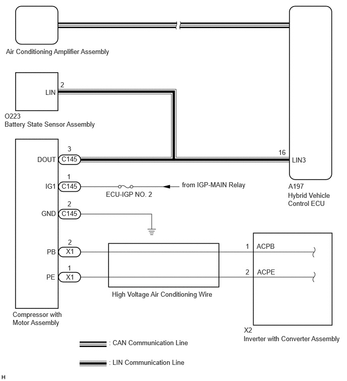
CAUTION / NOTICE / HINT
- CAUTION:
- ·
Before inspecting the high-voltage system, take safety precautions such as wearing insulated gloves and removing the service plug grip to prevent electrical shocks. After removing the service plug grip, put it in your pocket to prevent other technicians from accidentally reconnecting it while you are working on the high-voltage system.
·Do not touch the high-voltage connectors or terminals for 10 minutes after the service plug grip is removed.
- NOTICE:
- ·
Inspect the fuses for circuits related to this system before performing the following procedure.
·After turning the ignition switch off, waiting time may be required before disconnecting the cable from the negative (-) auxiliary battery terminal. Therefore, make sure to read the disconnecting the cable from the negative (-) auxiliary battery terminal notices before proceeding with work.
·When the cable is disconnected from the negative (-) auxiliary battery terminal, the memory of various systems will be cleared. Because of this, be sure to make a record of the contents memorized in each system before starting work. When work is finished, adjust each system to its previous state.
·The hybrid control system and air conditioning system output DTCs separately. Perform troubleshooting for the hybrid control system first if DTCs for both systems are output simultaneously.
·The air conditioning system uses the CAN communication system. Inspect the communication functions by following How to Proceed with Troubleshooting. Troubleshoot the air conditioning system after confirming that the communication systems are functioning properly.
PROCEDURE
Check if hybrid control system DTCs are output.
- Powertrain > Hybrid Control > Trouble Codes
- 50001 397
- Result:
Result Proceed to DTCs are not output A DTCs are output B
A
B
Disconnect the C145 compressor with motor assembly connector.
Disconnect the A197 hybrid vehicle control ECU connector.
Disconnect the O223 battery state sensor assembly connector.
Measure the resistance according to the value(s) in the table below.
- Standard Resistance:
Tester Connection Condition Specified Condition C145-3 (DOUT) - A197-16 (LIN3) Always Below 1 Ω C145-3 (DOUT) or A197-16 (LIN3) - Other terminals and body ground Always 10 kΩ or higher
- Result:
Proceed to OK NG
OK
NG
- CAUTION:
-
Do not disconnect the connector on the high-voltage side.
Measure the voltage and resistance according to the value(s) in the table below.
- Standard Voltage:
Tester Connection Switch Condition Specified Condition C145-1 (IG1) - Body ground Ignition switch ON 11 to 14 V
- Standard Resistance:
Tester Connection Condition Specified Condition C145-2 (GND) - Body ground Always Below 1 Ω
- Result:
Proceed to OK NG
OK
NG
- CAUTION:
-
Be sure to wear insulated gloves.
Remove the high voltage air conditioning wire.
- HINT:
Measure the resistance according to the value(s) in the table below.
- Standard Resistance:
Tester Connection Condition Specified Condition X1-2 (PB) - X2-1 (ACPB) Always Below 1 Ω X1-1 (PE) - X2-2 (ACPE) Always Below 1 Ω X1-2 (PB) - Other terminals and body ground Always 10 kΩ or higher
- Result:
Proceed to OK NG
OK
NG