POWER OUTLETS (INT) WIRELESS CHARGING SYSTEM Status Signal Circuit
DESCRIPTION
This circuit sends a charging suspension signal from the certification ECU (smart key ECU assembly) to the mobile wireless charger cradle assembly. Based on this signal, the mobile wireless charger cradle assembly suspends or resumes wireless charging.
WIRING DIAGRAM
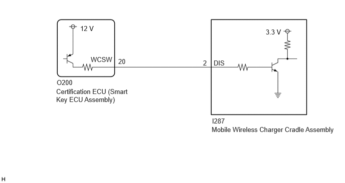
CAUTION / NOTICE / HINT
- NOTICE:
-
Before replacing the certification ECU (smart key ECU assembly), refer to Service Bulletin.
PROCEDURE
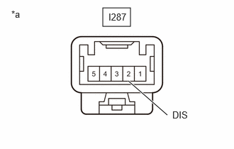
| *a | Component with harness connected
(Mobile Wireless Charger Cradle Assembly) |
Measure the voltage according to the value(s) in the table below.
- Standard Voltage:
Tester Connection Condition Specified Condition I287-2 (DIS) - Body ground For 2 seconds after turning ignition switch from off to ACC*1 4.5 to 6.0 V Device being charged Below 1 V Charging suspended due to entry and start system status*2 4.5 to 6.0 V
*1: When the ignition switch is turned from off to ACC, the mobile wireless charger cradle assembly monitors the charging suspension signal for 2 seconds. If the charging suspension signal is not 4 V or more for 0.8 seconds or more during monitoring, the mobile wireless charger cradle assembly determines that there is an open in the charging suspension signal line, blinks (pattern 2) the indicator light (red), and prohibits operation until the ignition switch is turned from off to ACC again.
*2: For details about conditions when the certification ECU (smart key ECU assembly) sends the charging suspension signal, refer to System Description.
- Result:
Proceed to OK NG
OK
NG
Disconnect the O200 certification ECU (smart key ECU assembly) connector.
Disconnect the I287 mobile wireless charger cradle assembly connector.
Measure the resistance according to the value(s) in the table below.
- Standard Resistance:
Tester Connection Condition Specified Condition O200-20 (WCSW) - I287-2 (DIS) Always Below 1 Ω O200-20 (WCSW) or I287-2 (DIS) - Body ground Always 10 kΩ or higher
- Result:
Proceed to OK NG
OK
NG