SUPPLEMENTAL RESTRAINT SYSTEMS KNEE AIRBAG ASSEMBLY INSTALLATION
CAUTION / NOTICE / HINT
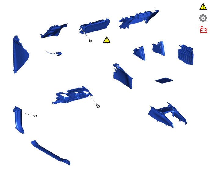
| Procedure | Part Name Code | 
|

|

|
|
|---|---|---|---|---|---|
| 1 | LOWER NO. 1 INSTRUMENT PANEL AIRBAG ASSEMBLY | 73900 | ( 202307,999999,_58,_115188,_0510625,RM100000002BZWH_01_0001,) 202307,999999,_58,_115188,_0510625,RM100000002BZWH_01_0001,)
|
- | - |
| 2 | LOWER CENTER INSTRUMENT PANEL FINISH PANEL | 55434F | - | - | - |
| 3 | LOWER INSTRUMENT PANEL FINISH PANEL | 55432B | - | - | - |
| 4 | HOOD LOCK CONTROL LEVER SUB-ASSEMBLY | 53601 | - | - | - |
| 5 | NO. 1 INSTRUMENT SIDE PANEL | 55317E | - | - | - |
| 6 | FRONT CONSOLE UPPER PANEL GARNISH | 58831A | - | - | - |
| 7 | NO. 2 BOX BOTTOM MAT | 58917 | - | - | - |
| 8 | NO. 2 CONSOLE UPPER PANEL GARNISH | 58834B | - | - | - |
| 9 | NO. 1 CONSOLE UPPER PANEL GARNISH | 58833B | - | - | - |
| 10 | FRONT NO. 1 CONSOLE BOX INSERT | 58816D | - | - | - |
| 11 | FRONT NO. 2 CONSOLE BOX INSERT | 58817A | - | - | - |
| 12 | NO. 1 INSTRUMENT PANEL UNDER COVER SUB-ASSEMBLY | 55606 | - | - | - |
| 13 | COWL SIDE TRIM SUB-ASSEMBLY LH | 62112A | - | - | - |
| 14 | FRONT DOOR SCUFF PLATE LH | 67914B | - | - | - |
| 15 | CONNECT CABLE TO NEGATIVE AUXILIARY BATTERY TERMINAL | - | - | - | - |
| 16 | INSPECT SRS WARNING LIGHT | - | (202307,999999,_58,_115188,_0510625,RM100000002BZWH_01_0235,)
|
- | - |
| 17 | INITIALIZATION AFTER RECONNECTING AUXILIARY BATTERY TERMINAL | - | - | - | (202307,999999,_58,_115188,_0510625,RM100000002BZWH_01_0237,)
|

|
Tightening torque for "Major areas involving basic vehicle performance such as moving/turning/stopping": N*m (kgf*cm, ft.*lbf) | - | - |
CAUTION / NOTICE / HINT
PROCEDURE

 73900
1.INSTALL LOWER NO. 1 INSTRUMENT PANEL AIRBAG ASSEMBLY
73900
1.INSTALL LOWER NO. 1 INSTRUMENT PANEL AIRBAG ASSEMBLY
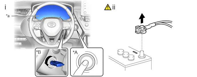
| *A | w/ Smart Entry and Start System | *B | w/o Smart Entry and Start System |
| *a | Illumination off | - | - |
Check that the ignition switch is off.
Check that the cable is disconnected from the negative (-) auxiliary battery terminal.
- CAUTION:
- ·
Wait at least 90 seconds after disconnecting the cable from the negative (-) auxiliary battery terminal to disable the SRS system.
- ·
If the airbag deploys for any reason, it may cause a serious accident.

Engage the hooks and claws to install the lower No. 1 instrument panel airbag assembly.
Install the 2 bolts.
- Torque:
- 10 N*m (102 kgf*cm, 7 ft.*lbf)
- NOTICE:
-
Confirm that the lower No. 1 instrument panel airbag assembly is installed securely without any excessive gaps and is not protruding outward.
Connect the airbag connector.
- NOTICE:
-
When connecting any airbag connector, take care not to damage the airbag wire harness.
- HINT:
-
Refer to How to Connect or Disconnect Airbag Connector:
55434F
2.INSTALL LOWER CENTER INSTRUMENT PANEL FINISH PANEL
55432B
3.INSTALL LOWER INSTRUMENT PANEL FINISH PANEL
53601
4.CONNECT HOOD LOCK CONTROL LEVER SUB-ASSEMBLY
55317E
5.INSTALL NO. 1 INSTRUMENT SIDE PANEL
58831A
6.INSTALL FRONT CONSOLE UPPER PANEL GARNISH
58917
7.INSTALL NO. 2 BOX BOTTOM MAT
58834B
8.INSTALL NO. 2 CONSOLE UPPER PANEL GARNISH
58833B
9.INSTALL NO. 1 CONSOLE UPPER PANEL GARNISH
58816D
10.INSTALL FRONT NO. 1 CONSOLE BOX INSERT
58817A
11.INSTALL FRONT NO. 2 CONSOLE BOX INSERT
55606
12.INSTALL NO. 1 INSTRUMENT PANEL UNDER COVER SUB-ASSEMBLY
62112A
13.INSTALL COWL SIDE TRIM SUB-ASSEMBLY LH
67914B
14.INSTALL FRONT DOOR SCUFF PLATE LH
15.CONNECT CABLE TO NEGATIVE AUXILIARY BATTERY TERMINAL
for M20A-FKS, M20C-FKS, M20E-FKS:
for M20F-FXS, M20G-FXS:
16.INSPECT SRS WARNING LIGHT
17. INITIALIZATION AFTER RECONNECTING AUXILIARY BATTERY TERMINAL
- HINT:
-
When disconnecting and reconnecting the auxiliary battery, there is an automatic learning function that completes learning when the respective system is used.