LIGHTING (INT) LIGHTING SYSTEM Push Start Switch Illumination Circuit
DESCRIPTION
The illuminated entry system controls the push start switch illumination.
WIRING DIAGRAM
for HEV Model
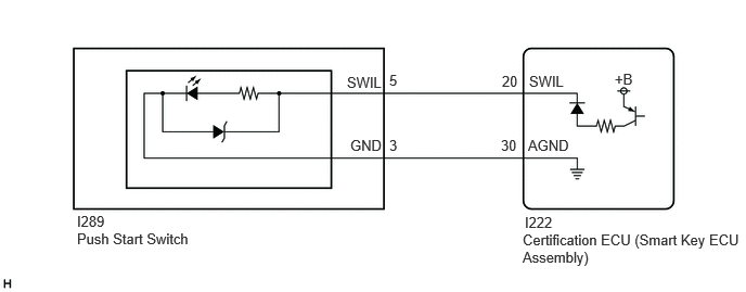
for Gasoline Model

CAUTION / NOTICE / HINT
- NOTICE:
-
Before replacing the certification ECU (smart key ECU assembly), refer to Service Bulletin.*1
*1: w/ Smart Entry and Start System
PROCEDURE
Check vehicle type.
- Result:
Result Proceed to for HEV Model A for Gasoline Model B
A
B
Perform the Active Test according to the display on the GTS.
- Body Electrical > Entry&Start > Active Test
-
Tester Display Measurement Item Control Range Diagnostic Note Start SW Light Power Supply Push start switch illumination OFF or ON -
- Body Electrical > Entry&Start > Active Test
-
Tester Display Start SW Light Power Supply - 50004 440 1
- OK:
Push start switch illumination comes on.
- Result:
Proceed to OK NG
OK
NG
- Result:
Proceed to OK NG
OK
NG
Disconnect the I222 certification ECU (smart key ECU assembly) connector.
Measure the resistance according to the value(s) in the table below.
- Standard Resistance:
Tester Connection Condition Specified Condition I289-5 (SWIL) - I222-20 (SWIL) Always Below 1 Ω I289-3 (GND) - I222-30 (AGND) Always Below 1 Ω I289-5 (SWIL) or I222-20 (SWIL) - Body ground Always 10 kΩ or higher I289-3 (GND) or I222-30 (AGND) - Body ground Always 10 kΩ or higher
- Result:
Proceed to OK NG
OK
NG
Perform the Active Test according to the display on the GTS.
- Body Electrical > Entry&Start > Active Test
-
Tester Display Measurement Item Control Range Diagnostic Note Start SW Light Power Supply Push start switch illumination OFF or ON -
- Body Electrical > Entry&Start > Active Test
-
Tester Display Start SW Light Power Supply - 50004 440 1
- OK:
Push start switch illumination comes on.
- Result:
Proceed to OK NG
OK
NG
- Result:
Proceed to OK NG
OK
NG
Disconnect the I222 certification ECU (smart key ECU assembly) connector.
Measure the resistance according to the value(s) in the table below.
- Standard Resistance:
Tester Connection Condition Specified Condition I35-5 (SWIL) - I222-20 (SWIL) Always Below 1 Ω I35-3 (GND) - I222-30 (AGND) Always Below 1 Ω I35-5 (SWIL) or I222-20 (SWIL) - Body ground Always 10 kΩ or higher I35-3 (GND) or I222-30 (AGND) - Body ground Always 10 kΩ or higher
- Result:
Proceed to OK NG
OK
NG