FRONT SUSPENSION FRONT STABILIZER BAR REMOVAL
CAUTION / NOTICE / HINT
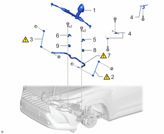
| Procedure | Part Name Code | 
|

|

|
|
|---|---|---|---|---|---|
| 1 | STEERING LINK ASSEMBLY | - | - | - | - |
| 2 | FRONT STABILIZER LINK ASSEMBLY LH | 48810 | ( 202307,999999,_53,_112966,_0502994,RM100000002BYS3_01_0053,) 202307,999999,_53,_112966,_0502994,RM100000002BYS3_01_0053,)
|
- | - |
| 3 | FRONT STABILIZER LINK ASSEMBLY RH | 48820B | (202307,999999,_53,_112966,_0502994,RM100000002BYS3_01_0054,)
|
- | - |
| 4 | WIRE HARNESS CLAMP BRACKET | - | - | - | - |
| 5 | FRONT NO. 1 STABILIZER BRACKET LH | 48829A | - | - | - |
| 6 | FRONT NO. 1 STABILIZER BRACKET RH | 48824A | - | - | - |
| 7 | FRONT STABILIZER BAR | 48811 | (202307,999999,_53,_112966,_0502994,RM100000002BYS3_01_0057,)
|
- | - |
| 8 | FRONT STABILIZER BAR BUSH LH | 48815E | - | - | - |
| 9 | FRONT STABILIZER BAR BUSH RH | 48815D | - | - | - |
CAUTION / NOTICE / HINT
The necessary procedures (adjustment, calibration, initialization, or registration) that must be performed after parts are removed and installed, or replaced during front stabilizer bar removal/installation are shown below.
| Replacement Part or Procedure | Necessary Procedures | Effect/Inoperative Function When Necessary Procedures are not Performed | Link |
|---|---|---|---|
|
*1: for HEV Model *2: for Gasoline Model |
|||
| Front wheel alignment adjustment | Calibration | ·
DTCs are stored ·
ABS warning light illuminates ·
Slip indicator light illuminates ·
VSC disabled or malfunctions |
(202307,999999,_54,_112606,_0608077,RM100000002C79U,)*1
( 202307,999999,_54,_112606,_0608078,RM100000002C7D1,)*2
|
| Suspension, tires, etc. | Parking assist ECU initialization | Panoramic view monitor system | (202201,999999,_56,_111969,_0587004,RM1000000029RN8,)
|
PROCEDURE

 1.REMOVE STEERING LINK ASSEMBLY
48810
2.REMOVE FRONT STABILIZER LINK ASSEMBLY LH
|
|
|
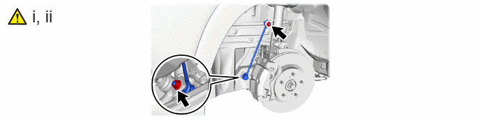
Remove the 2 nuts and front stabilizer link assembly LH.
If the ball joint turns together with the nut, use a 6 mm hexagon socket wrench to hold the stud bolt.
48820B
3.REMOVE FRONT STABILIZER LINK ASSEMBLY RH
Use the same procedure as for the LH side.
4.SEPARATE WIRE HARNESS CLAMP BRACKET
48829A
5.REMOVE FRONT NO. 1 STABILIZER BRACKET LH
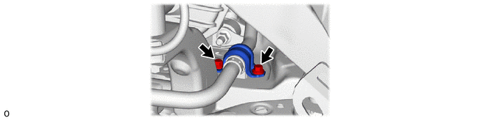
48824A
6.REMOVE FRONT NO. 1 STABILIZER BRACKET RH
Use the same procedure as for the LH side.
48811
7.REMOVE FRONT STABILIZER BAR
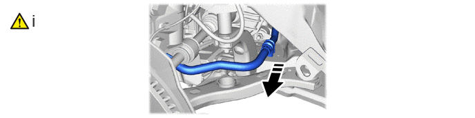

|
Remove in this Direction | - | - |
Remove the front stabilizer bar and 2 front stabilizer bar bushes as shown in the illustration.
48815E
8.REMOVE FRONT STABILIZER BAR BUSH LH
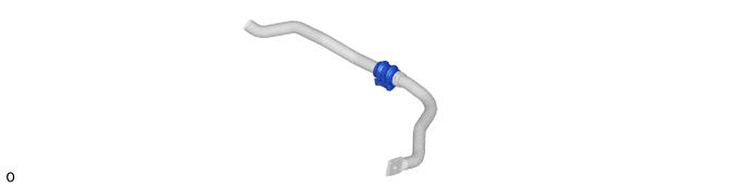
48815D
9.REMOVE FRONT STABILIZER BAR BUSH RH
Use the same procedure as for the LH side.