STEERING GEAR / LINKAGE STEERING GEAR REMOVAL
CAUTION / NOTICE / HINT
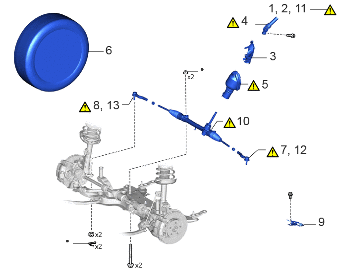
| Procedure | Part Name Code | 
|

|

|
|
|---|---|---|---|---|---|
| 1 | ALIGN FRONT WHEELS FACING STRAIGHT AHEAD | - | ( 202307,999999,_55,_112968,_0503003,RM100000002C3MP_01_0123,) 202307,999999,_55,_112968,_0503003,RM100000002C3MP_01_0123,)
|
- | - |
| 2 | SECURE STEERING WHEEL | - | (202307,999999,_55,_112968,_0503003,RM100000002C3MP_01_0124,)
|
- | - |
| 3 | COLUMN HOLE COVER SILENCER SHEET | 45259A | - | - | - |
| 4 | NO. 2 STEERING INTERMEDIATE SHAFT ASSEMBLY | 45260 | (202307,999999,_55,_112968,_0503003,RM100000002C3MP_01_0131,)
|
- | - |
| 5 | NO. 1 STEERING COLUMN HOLE COVER SUB-ASSEMBLY | 45025D | (202307,999999,_55,_112968,_0503003,RM100000002C3MP_01_0013,)
|
- | - |
| 6 | FRONT WHEELS | - | - | - | - |
| 7 | SEPARATE TIE ROD END SUB-ASSEMBLY LH | 45047 | (202307,999999,_55,_112968,_0503003,RM100000002C3MP_01_0109,)
|
- | - |
| 8 | SEPARATE TIE ROD END SUB-ASSEMBLY RH | 45046 | (202307,999999,_55,_112968,_0503003,RM100000002C3MP_01_0109,)
|
- | - |
| 9 | WIRING HARNESS CLAMP BRACKET | 82715Z | - | - | - |
| 10 | REMOVE STEERING LINK ASSEMBLY | - | (202307,999999,_55,_112968,_0503003,RM100000002C3MP_01_0126,)
|
- | - |
| 11 | SECURE STEERING LINK ASSEMBLY | - | (202307,999999,_55,_112968,_0503003,RM100000002C3MP_01_0130,)
|
- | - |
| 12 | REMOVE TIE ROD END SUB-ASSEMBLY LH | 45047 | (202307,999999,_55,_112968,_0503003,RM100000002C3MP_01_0127,)
|
- | - |
| 13 | REMOVE TIE ROD END SUB-ASSEMBLY RH | 45046 | (202307,999999,_55,_112968,_0503003,RM100000002C3MP_01_0127,)
|
- | - |
| ● | Non-reusable part | - | - |
CAUTION / NOTICE / HINT
The necessary procedures (adjustment, calibration, initialization, or registration) that must be performed after parts are removed and installed, or replaced during steering gear assembly removal/installation are shown below.
| Replacement Part or Procedure | Necessary Procedures | Effect/Inoperative Function When Necessary Procedures are not Performed | Link |
|---|---|---|---|
|
*1: for HEV Model *2: for Gasoline Model |
|||
| Front wheel alignment adjustment | Calibration | ·
DTCs are stored ·
ABS warning light illuminates ·
Slip indicator light illuminates ·
VSC disabled or malfunctions |
(202307,999999,_54,_112606,_0608077,RM100000002C79U,)*1
( 202307,999999,_54,_112606,_0608078,RM100000002C7D1,)*2
|
| Suspension, tires, etc. | Parking assist ECU initialization | Panoramic view monitor system | (202201,999999,_56,_111969,_0587004,RM1000000029RN8,)
|
| Steering gear assembly | End position initial setting | Power steering system | (202307,999999,_55,_112287,_0500993,RM100000002C2X3,)
|
PROCEDURE

 1. ALIGN FRONT WHEELS FACING STRAIGHT AHEAD
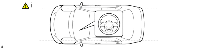
Align the front wheels facing straight ahead.
2. SECURE STEERING WHEEL
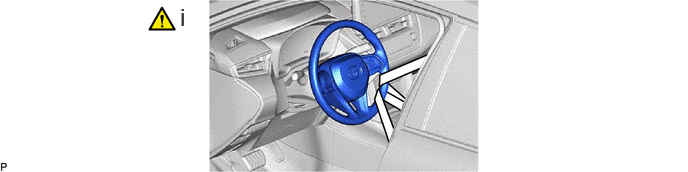
Secure the steering wheel with the seat belt to prevent damage to the spiral cable by rotation of the steering wheel.
45259A
3.REMOVE COLUMN HOLE COVER SILENCER SHEET
45260
4.SEPARATE NO. 2 STEERING INTERMEDIATE SHAFT ASSEMBLY
45025D
5.SEPARATE NO. 1 STEERING COLUMN HOLE COVER SUB-ASSEMBLY
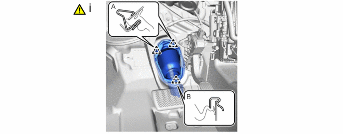
Separate the clip (A), disengage the clip (B) from the vehicle body and separate the No. 1 steering column hole cover sub-assembly.
- NOTICE:
-
Do not damage the clips (A) or (B).
6.REMOVE FRONT WHEELS
45047
7.SEPARATE TIE ROD END SUB-ASSEMBLY LH
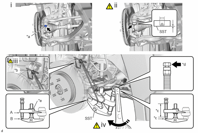
| *a | Cotter Pin | *b | String |
| *c | Molybdenum Grease Application Area | *d | Place wrench here |
| *e | Center Nut | - | - |

|
Turn | - | - |
Remove the cotter pin and nut.
Install SST to the tie rod end sub-assembly LH.
- SST
- 09960-20010 (09961-02060)
- NOTICE:
-
Make sure that the lower ends of the tie rod end sub-assembly LH and SST are aligned.
Secure SST using a string.
- NOTICE:
-
Be sure to tighten the string firmly to secure SST to the steering knuckle LH to prevent SST from falling off.
Using SST, separate the tie rod end sub-assembly LH from the steering knuckle LH.
- SST
- 09960-20010 (09961-02010)
- CAUTION:
-
Apply molybdenum grease to the bolt threads and the tip of SST.
- NOTICE:
- ·
Be sure to tighten the string firmly to secure SST to the steering knuckle LH to prevent SST from falling off.
·Install SST with the center nut so that (A) and (B) shown in the illustration are parallel. Otherwise, the ball joint dust cover may be damaged.
·Be sure to place the wrench on the part shown in the illustration.
·Do not damage the front disc brake dust cover.
·Do not damage the ball joint dust cover.
·Do not damage the steering knuckle LH.
45046
8.SEPARATE TIE ROD END SUB-ASSEMBLY RH
Perform the same procedure as for the LH side.
82715Z
9.SEPARATE WIRING HARNESS CLAMP BRACKET

10.REMOVE STEERING LINK ASSEMBLY
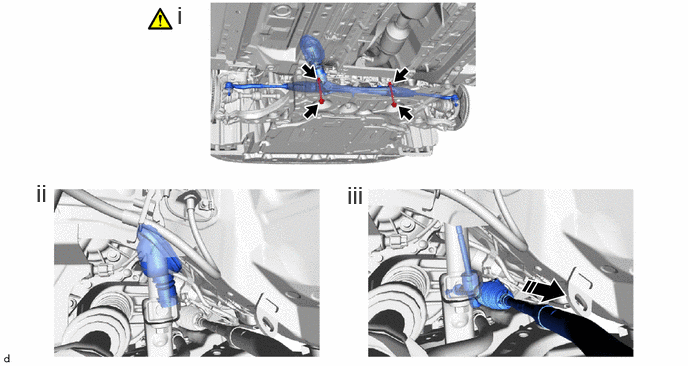
|
|
Remove in this Direction | - | - |
Remove the 2 bolts and 2 nuts to separate the steering link assembly.
- NOTICE:
-
Because the nut has its own stopper, do not turn the nut. Loosen the bolt with the nut secured.
Remove the No. 1 steering column hole cover sub-assembly from the steering link assembly.
Remove the steering link assembly as shown in the illustration.
11.SECURE STEERING LINK ASSEMBLY
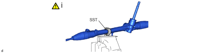
Using SST with wrapped in protective tape, secure the steering link assembly in a vise.
- SST
- 09612-00012
45047
12.REMOVE TIE ROD END SUB-ASSEMBLY LH

| *a | Matchmark | - | - |
Put matchmarks on the tie rod end sub-assembly LH and steering gear assembly.
Remove the tie rod end sub-assembly LH and lock nut.
45046
13.REMOVE TIE ROD END SUB-ASSEMBLY RH
Perform the same procedure as for the LH side.