RM38T0EC _51 Engine / Hybrid System _144956 M20F-FXS, M20G-FXS ENGINE CONTROL _0604911 SFI SYSTEM J

M20F-FXS, M20G-FXS ENGINE CONTROL  SFI SYSTEM  MIL Circuit  


DESCRIPTION

The Malfunction Indicator Lamp (MIL) is used to indicate vehicle malfunctions detected by the ECM.

The MIL operation can be checked visually. When the ignition switch is first to ON, the MIL should be illuminated and should then turn off after the engine is started. If the MIL remains illuminated or is not illuminated, conduct the following troubleshooting procedure using the GTS.

WIRING DIAGRAM
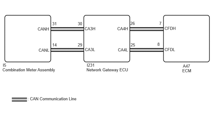
A529045E03
1.26,0.885 1.875,1.083 0.615,0.198 10 false CANH 1.292,1.594 1.906,1.792 0.615,0.198 10 false CANL 2.833,0.875 3.448,1.073 0.615,0.198 10 false CA3H 5.51,1.573 6.125,1.771 0.615,0.198 10 false CFDL 5.51,0.865 6.125,1.063 0.615,0.198 10 false CFDH 2.844,1.573 3.458,1.771 0.615,0.198 10 false CA3L 3.927,0.875 4.542,1.073 0.615,0.198 10 false CA4H 3.948,1.583 4.563,1.781 0.615,0.198 10 false CA4L 0.927,3.219 3.042,3.51 2.115,0.292 10 false : CAN Communication Line 2.896,2.25 4.438,2.5 1.542,0.25 10 false Network Gateway ECU 0.083,2.25 2.021,2.573 1.938,0.323 10 false Combination Meter Assembly 6.104,2.281 6.615,2.563 0.51,0.281 10 false ECM 6.125,2.125 6.74,2.323 0.615,0.198 10 false A47 2.906,2.094 3.521,2.292 0.615,0.198 10 false I231 0.094,2.094 0.708,2.292 0.615,0.198 10 false I5 1.75,0.708 2.365,0.906 0.615,0.198 10 false 31 1.75,1.417 2.365,1.615 0.615,0.198 10 false 14 2.604,0.708 3.219,0.906 0.615,0.198 10 false 30 2.604,1.417 3.219,1.615 0.615,0.198 10 false 29 4.365,0.698 4.979,0.896 0.615,0.198 10 false 26 4.375,1.417 4.99,1.615 0.615,0.198 10 false 25 5.333,0.698 5.948,0.896 0.615,0.198 10 false 7 5.271,1.396 5.885,1.594 0.615,0.198 10 false 8

PROCEDURE

1.CHECK THAT MIL IS ILLUMINATED
a.

Perform troubleshooting in accordance with the table below.


Result:
MIL Condition Proceed to
Illuminates → Turns off Ignition switch ON → engine is started A
Other than above - B


A

B

2.CHECK COMMUNICATION BETWEEN GTS AND ECM
a.

Check the communication between the GTS and ECM.

HINT:

It can be checked using the "Engine" item of the Data List.


Result:
Result Proceed to
Communication is possible A
Communication is not possible B


A

3.CHECK WHETHER DTC OUTPUT RECURS

B

3.CHECK WHETHER DTC OUTPUT RECURS
a.

Perform the Health Check using the GTS.


b.

Check if any DTCs have been detected. Note down any DTCs.


Result:
Result Proceed to
DTCs are not output A
Any DTCs is output B


HINT:

Check for detected DTCs output from other ECUs which relate to the MIL.


A

4.PERFORM ACTIVE TEST USING GTS

B

REPAIR CIRCUIT INDICATED BY OUTPUT

4.PERFORM ACTIVE TEST USING GTS
a.

Enter the following menus.

Body Electrical > Combination Meter > Active Test
Tester Display
Check Engine Warning
50004 409 64

b.

Check the status of the MIL while performing the Active Test.

Result:
Result Proceed to
Changes A
Does not change B


A

B