M20F-FXS, M20G-FXS FUEL FUEL SYSTEM PRECAUTION
- CAUTION:
- ·
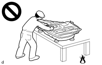
Never perform work on fuel system components near any possible ignition sources.
·Vaporized fuel could ignite, resulting in a serious accident.
·
Do not perform work on fuel system components without first disconnecting the cable from the negative (-) auxiliary battery terminal.
·Sparks could cause vaporized fuel to ignite, resulting in a serious accident.
·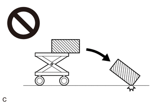
The fuel tank assembly is very heavy. Be sure to follow the procedure described in the repair manual, or the fuel tank assembly may fall off the engine lifter.
·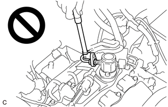
To prevent serious injury due to fuel spray from the high-pressure fuel lines, always discharge fuel system pressure before removing any fuel system components.
BEFORE WORKING ON FUEL SYSTEM
Before inspecting and repairing the fuel system, disconnect the cable from the negative (-) auxiliary battery terminal.
- NOTICE:
-
After turning the power switch off, waiting time may be required before disconnecting the cable from the negative (-) auxiliary battery terminal.
Do not smoke or work near fire when handling the fuel system.
Keep fuel away from rubber or leather parts.
DISCHARGE FUEL SYSTEM PRESSURE
- CAUTION:
- ·
Make sure the engine coolant temperature is 60°C (140°F) or less when performing this procedure.
·Do not disconnect any part of the fuel system until you have discharged the fuel system pressure.
·Pressure will still remain in the fuel lines even after performing the following procedure. When disconnecting a fuel line, cover it with a piece of cloth to prevent fuel from spraying or coming out.
When discharging fuel system pressure by disconnecting the EFI-MAIN NO. 2 relay:
Remove the No. 2 relay block cover.
Remove the EFI-MAIN NO. 2 relay.
Remove the No. 1 engine under cover assembly.
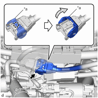
| *a | Lock Lever |
Disengage the claw and raise the lock lever to disconnect the No. 6 engine wire connector as shown in the illustration.
Connect the GTS to the DLC3.
Turn the power switch on (IG).
Turn the GTS on.
Put the engine in Inspection Mode (Maintenance Mode).
- Powertrain > Hybrid Control > Utility
-
Tester Display Inspection Mode - 50005 397 2103
Start the engine. After the engine has stopped on its own, turn the power switch off.
- NOTICE:
-
Do not increase the engine speed or drive the vehicle while waiting for the engine to stop on its own.
Crank the engine again and make sure that the engine does not start.
- HINT:
-
DTC P008700 (Fuel Rail/System Pressure - Too Low), P017100 (System Too Lean Bank 1), P319000 (Poor Engine Power), P319100 (Engine does not Start) or P319300 (Fuel Run Out) may be stored. Clear the DTCs before proceeding to the next step.
- ··
Hybrid control system DTC:
Remove the fuel tank cap assembly and discharge the pressure from the fuel tank assembly.
Disconnect the cable from the negative (-) auxiliary battery terminal.
- NOTICE:
-
When disconnecting the cable, some systems need to be initialized after the cable is reconnected.
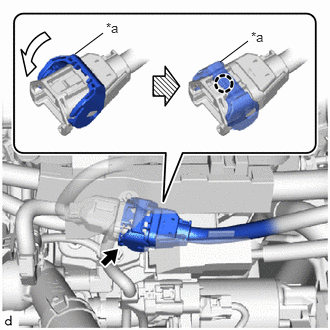
| *a | Lock Lever |
Connect the No. 6 engine wire connector and push down the lock lever to engage the claw as shown in the illustration.
Install the No. 1 engine under cover assembly.
Install the EFI-MAIN NO. 2 relay.
Install the No. 2 relay block cover.
When discharging fuel system pressure by disconnecting the fuel pump connector:
Remove the rear floor service hole cover.
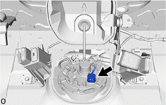
Disconnect the fuel pump connector.
Remove the No. 1 engine under cover assembly.
| *a | Lock Lever |
Disengage the claw and raise the lock lever to disconnect the No. 6 engine wire connector as shown in the illustration.
Connect the GTS to the DLC3.
Turn the power switch on (IG).
Turn the GTS on.
Put the engine in Inspection Mode (Maintenance Mode).
- Powertrain > Hybrid Control > Utility
-
Tester Display Inspection Mode - 50005 397 2103
Start the engine. After the engine has stopped on its own, turn the power switch off.
- NOTICE:
-
Do not increase the engine speed or drive the vehicle while waiting for the engine to stop on its own.
Crank the engine again and make sure that the engine does not start.
- HINT:
-
DTC P008700 (Fuel Rail/System Pressure - Too Low), P017100 (System Too Lean Bank 1), P319000 (Poor Engine Power), P319100 (Engine does not Start) or P319300 (Fuel Run Out) may be stored. Clear the DTCs before proceeding to the next step.
- ··
Hybrid control system DTC:
Remove the fuel tank cap assembly and discharge the pressure from the fuel tank assembly.
Disconnect the cable from the negative (-) auxiliary battery terminal.
- NOTICE:
-
When disconnecting the cable, some systems need to be initialized after the cable is reconnected.
| *a | Lock Lever |
Connect the No. 6 engine wire connector and push down the lock lever to engage the claw as shown in the illustration.
Install the No. 1 engine under cover assembly.
Connect the fuel pump connector.
Install the rear floor service hole cover.
FUEL LINE
When disconnecting a high-pressure fuel line, a large amount of fuel will spray. Perform the following procedure:
Discharge fuel system pressure.
Disconnect the fuel tube.
Drain the fuel remaining inside the fuel tube into a container.
Cover the disconnected fuel pipe and fuel tube connector with plastic bags to prevent damage and contamination.
Quick Type A:
Perform the following procedure when disconnecting a fuel tube connector.
- NOTICE:
-
Remove any foreign matter on the fuel tube connector and fuel pipe before performing this work.

|
Open |

|
Pull |
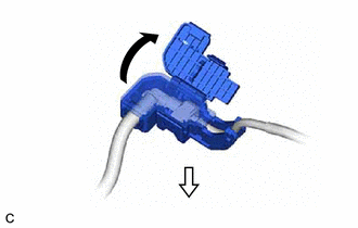
Open the cover of the EFI fuel pipe clamp and remove the EFI fuel pipe clamp from the fuel tube connector.
Check that there is no foreign matter around the fuel tube connector before disconnecting it. Clean it if necessary.
| *a | Retainer |
|
|
Retainer Holding Position |
|
|
Pull out |
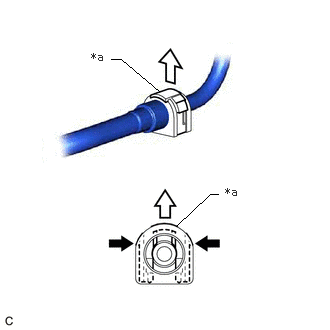
While holding the retainer at the positions shown in the illustration, pull up the retainer to disengage the lock claws.
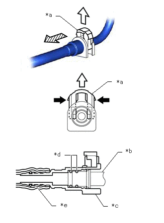
| *a | Retainer |
| *b | Fuel Pipe |
| *c | Fuel Tube Connector |
| *d | O-ring |
| *e | Nylon Tube |
|
|
Retainer Holding Position |
|
|
Pull out |

|
Pull off |
Pull up the retainer while holding it at the positions shown in the illustration and pull off the fuel tube connector.
If the fuel tube connector and fuel pipe are stuck, push and pull the fuel tube connector to release it. Pull the fuel tube connector off of the fuel pipe carefully.
- NOTICE:
- ·
Do not scratch or allow any foreign matter to get on the parts when disconnecting them as the fuel tube connector has O-rings that seal the pipe (fuel pipe).
·Do not bend, twist, pinch or kink the nylon tube.
Check that there is no foreign matter on the sealing surfaces of the disconnected fuel lines. Clean them if necessary.
Cover the disconnected fuel pipe and fuel tube connector with plastic bags to prevent damage and contamination.
Quick Type A:
Perform the following procedure when connecting a fuel tube connector.
- NOTICE:
-
Check that there is no damage or foreign matter on the connecting parts of the fuel lines.
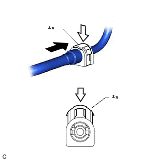
| *a | Retainer |
|
|
Push |
|
|
Push in |
Align the fuel tube connector with the fuel pipe, push the fuel tube connector onto the fuel pipe, then push in the retainer to secure the connection.
- NOTICE:
-
Confirm that the retainer makes a "click" sound when pushed.
- HINT:
-
If it is difficult to push the fuel tube connector onto the fuel pipe, apply a small amount of clean gasoline to the tip of the fuel pipe.
After connecting the fuel lines, check that the fuel pipe and fuel tube connector are securely connected by pulling on them.
Install the EFI fuel pipe clamp to the fuel tube connector and close the cover of the EFI fuel pipe clamp.
Quick Type B:
Perform the following procedure when disconnecting a fuel tube connector.
- NOTICE:
-
Remove any foreign matter on the fuel tube connector and fuel pipe before performing this work.
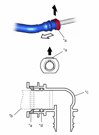
| *a | Retainer |
| *b | Fuel Pipe |
| *c | Fuel Tube Connector |
| *d | O-ring |
|
|
Pull out |
|
|
Pull off |
Pull out the retainer to disengage the lock claws and pull off the fuel tube connector.
If the fuel tube connector and fuel pipe are stuck, push and pull the fuel tube connector to release it. Pull the fuel tube connector off of the fuel pipe carefully.
- NOTICE:
-
Do not scratch or allow any foreign matter to get on the parts when disconnecting them as the fuel tube connector has O-rings that seal the pipe (fuel pipe).
Check that there is no foreign matter on the sealing surfaces of the disconnected fuel lines. Clean them if necessary.
Cover the disconnected fuel pipe and fuel tube connector with plastic bags to prevent damage and contamination.
Quick Type B:
Perform the following procedure when connecting a fuel tube connector.
- NOTICE:
-
Check that there is no damage or foreign matter on the connecting parts of the fuel lines.
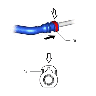
| *a | Retainer |
|
|
Push |
|
|
Push in |
Align the fuel tube connector with the fuel pipe, push the fuel tube connector onto the fuel pipe, then push in the retainer to secure the connection.
- NOTICE:
-
Confirm that the retainer makes a "click" sound when pushed.
- HINT:
-
If it is difficult to push the fuel tube connector onto the fuel pipe, apply a small amount of clean gasoline to the tip of the fuel pipe.
After connecting the fuel lines, check that the fuel pipe and fuel tube connector are securely connected by pulling on them.
Quick Type C:
Perform the following procedure when disconnecting a fuel tube connector.
- NOTICE:
-
Remove any foreign matter on the fuel tube connector and fuel pipe before performing this work.
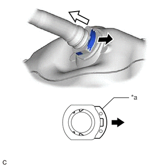
| *a | Retainer |
|
|
Pull out |
|
|
Pull off |
Pull out the retainer to disengage the lock claws and pull off the fuel tube connector.
If the fuel tube connector and fuel pipe are stuck, push and pull the fuel tube connector to release it. Pull the fuel tube connector off of the fuel pipe carefully.
- NOTICE:
-
Do not scratch or allow any foreign matter to get on the parts when disconnecting them as the fuel tube connector has O-rings that seal the pipe (fuel pipe).
Check that there is no foreign matter on the sealing surfaces of the disconnected fuel lines. Clean them if necessary.
Cover the disconnected fuel pipe and fuel tube connector with plastic bags to prevent damage and contamination.
Quick Type C:
Perform the following procedure when connecting a fuel tube connector.
- NOTICE:
-
Check that there is no damage or foreign matter on the connecting parts of the fuel lines.

| *a | Retainer |
|
|
Push |
|
|
Push in |
Align the fuel tube connector with the fuel pipe, push the fuel tube connector onto the fuel pipe, then push in the retainer to secure the connection.
- NOTICE:
-
Confirm that the retainer makes a "click" sound when pushed.
- HINT:
- ·
If it is difficult to push the fuel tube connector onto the fuel pipe, apply a small amount of clean gasoline to the tip of the fuel pipe.
·Make sure the retainer is positioned within the area shown in the illustration.
After connecting the fuel lines, check that the fuel pipe and fuel tube connector are securely connected by pulling on them.
FUEL SUCTION TUBE WITH PUMP AND GAUGE ASSEMBLY
- NOTICE:
-
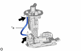 0.667,1.198 1,1.198 false 0.479,1.104 0.792,1.26 0.313,0.156 10 false *a
*a Tube
-
Do not disconnect the tube shown in the illustration when disassembling the fuel suction tube with pump and gauge assembly. Doing so will cause reassembly of the fuel suction tube with pump and gauge assembly to be impossible as the tube is pressed into the fuel suction plate sub-assembly.
INSPECT FOR FUEL LEAK
Check that there are no fuel leaks from the fuel system after doing any maintenance or repairs.