HYBRID / BATTERY CONTROL HV BATTERY CHARGING
CAUTION / NOTICE / HINT
- CAUTION:
- ·
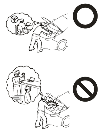
Orange wire harnesses and connectors indicate high-voltage circuits. To prevent electric shock, always follow the procedure described in the repair manual.
·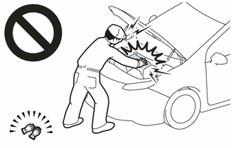
To prevent electric shock, wear insulated gloves when working on wire harnesses and components of the high voltage system.
- HINT:
-
When the cable is disconnected / reconnected to the auxiliary battery terminal, systems temporarily stop operating. However, each system has a function that completes learning the first time the system is used.
- ·
Learning completes when vehicle is driven.
Effect/Inoperative Function When Necessary Procedures are not Performed Necessary Procedures Link Front Camera System Drive the vehicle straight ahead at 15 km/h (10 mph) or more for 1 second or more. (  202307,999999,_95,_112293,_0586709,RM100000002BSVY,)
·Learning completes when vehicle is operated normally
Effect/Inoperative Function When Necessary Procedures are not Performed Necessary Procedures Link Power door lock control system
·Back door opener
Perform door unlock operation with door control switch or electrical key transmitter sub-assembly switch. ( 202201,999999,_58,_115226,_0510939,RM1000000020BSY,)
Power back door system Fully close the back door by hand.
- HINT:
-
Initialization is not necessary if the above procedures are performed while the back door is closed.
( 202201,999999,_59,_113746,_0504731,RM100000001ZJKP,)
Air conditioning system After the ignition switch is turned to ON, the servo motor standard position is recognized. -
PROCEDURE

 1. PRECAUTION
- NOTICE:
-
After turning the ignition switch off, waiting time may be required before disconnecting the cable from the negative (-) auxiliary battery terminal.
2.INSPECT AUXILIARY BATTERY VOLTAGE
Measure the auxiliary battery voltage.
- Standard Voltage:
Approximately 11 V or more
- HINT:
- ·
The horn should sound clearly.
·If the voltage is 10 V or less, either charge the auxiliary battery (charging usually takes about 1 hour), or replace it with an auxiliary battery that is already charged.
3. PREPARATION FOR HV BATTERY CHARGING
- CAUTION:
- ·
The hybrid system has high-voltage circuits. Accidents, such as electric shock, or electric leaks may result if the hybrid system is not operated in a correct manner. Make sure to follow the correct procedure.
·Wear insulated gloves.
- HINT:
- ·
Removing the service plug grip interrupts the high voltage circuit.
·High voltage wiring connectors are orange.
Check the SOC (State of Charge) of the HV battery.
If the hybrid system fails to start and "Traction Battery Needs to be Protected Shift into [P] to Restart" or "Traction Battery Needs to be Protected Refrain From the Use of [N] Position" is displayed on the multi-information display, the HV battery may be discharged.
Confirm if the engine starts. If the engine starts, leave it idling with the shift lever in P until the engine stops (self charge has completed).
If the engine cannot start, follow the procedure to charge the HV battery.
- HINT:
- ·
Before performing external charging, always use the GTS to perform troubleshooting.
·Charging time using the THS charger is 10 minutes per charge cycle. The charging time when using a THS charger is a short charging time (when the HV battery temperature is 25°C (77°F), 10 minutes may be sufficient, if the HV battery temperature is 0°C (32°F), then three 10 minute charge cycles may be required) for putting the engine in a condition where it can be started (the system can enter the READY-on state). (The THS charger will automatically stop 10 minutes after charging starts.)
Remove the service plug grip.
Check the terminal voltage.
Remove the connector cover assembly.
Check the terminal voltage.
Install the connector cover assembly.
Disconnect rear center seat outer belt assembly.
Remove the bench type rear seat cushion assembly.
Remove the rear seat cushion lock hook.
Remove the rear under side cover LH.
Remove the rear under side cover RH.
Remove the rear under cover.
Remove the rear seat cushion leg sub-assembly.
Remove the No. 1 hybrid battery shield sub-assembly.
Disconnect the floor under wire.
Inspect the electrical insulation of the HV battery.
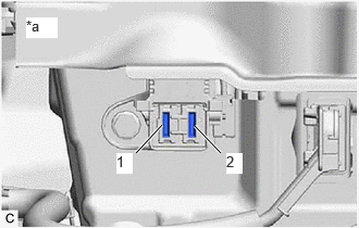
| *a | Service Plug Grip Removed
(Service Plug Grip Connecting Terminals) |
Using a megohmmeter set to 500 V, measure the resistance according to the value(s) in the table below.
- NOTICE:
-
Be sure to set the megohmmeter to 500 V when performing this test. Using a setting higher than 500 V can result in damage to the component being inspected.
- Standard Resistance:
Tester Connection Condition Specified Condition 1 - Body ground Ignition switch off 10 MΩ or higher 2 - Body ground Ignition switch off 10 MΩ or higher

| *a | Component without harness connected
(HV Battery Junction Block Assembly) |
Using a megohmmeter set to 500 V, measure the resistance according to the value(s) in the table below.
- NOTICE:
-
Be sure to set the megohmmeter to 500 V when performing this test. Using a setting higher than 500 V can result in damage to the component being inspected.
- Standard Resistance:
Tester Connection Condition Specified Condition W7-1 (CBI) - Body ground Ignition switch off 10 MΩ or higher W6-1 (CEI) - Body ground Ignition switch off 10 MΩ or higher
Connect the THS charger in the order shown in the illustration.
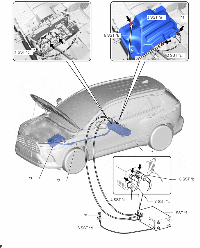
| *1 | HV Battery | *2 | HV Floor Under Wire |
| *3 | Inverter with Converter Assembly | *4 | No. 1 HV Battery Cover Panel RH |
| *a | EV Bonding Cable (Green Cable) | *b | Low Voltage Cable |
| *c | High Voltage Cable | *d | Power Input Plug |
| *e | Grounded AC 100 to 240 V Receptacle | *f | THS Charger |
- NOTICE:
- ·
Make sure to connect the EV bonding cable first to prevent electrical shock.
·Connect all of the THS charger cables in the order shown in the illustration to prevent electrical shock.
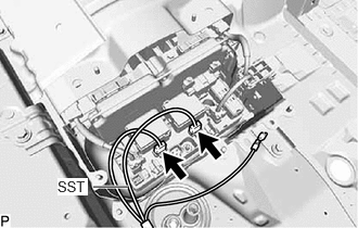
Connect the 2 SST (high voltage cable) connectors to the HV battery junction block assembly.
- SST
- 09882-10090
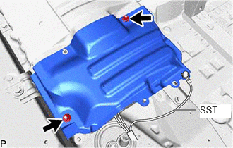
Temporarily install the No. 1 HV battery cover panel RH with the 2 nuts.
- Torque:
- 7.5 N*m (76 kgf*cm, 66 in.*lbf)
- NOTICE:
-
Be careful not to pinch SST (high voltage cable).
Connect the SST (high voltage cable) terminal to the position shown in the illustration with the nut.
- Torque:
- 7.5 N*m (76 kgf*cm, 66 in.*lbf)
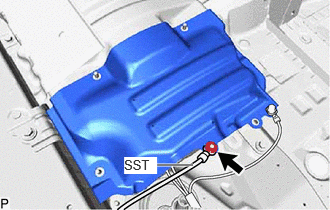
Connect SST (EV bonding cable (green cable)) to the position shown in the illustration with the nut.
- SST
- 09882-10070
- Torque:
- 7.5 N*m (76 kgf*cm, 66 in.*lbf)
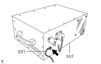
Connect SST (EV bonding cable (green cable)) to SST (THS charger).
- SST
- 09880-10021 (09881-10041)
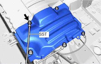
Connect SST (low voltage cable) to the position shown in the illustration with the nut.
- Torque:
- 7.5 N*m (76 kgf*cm, 66 in.*lbf)
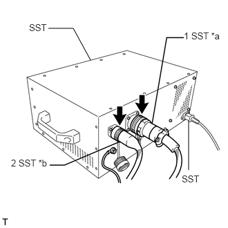
| *a | Low Voltage Cable |
| *b | High Voltage Cable |
Connect SST (low voltage cable) and SST (high voltage cable) to SST (THS charger) in the order shown in the illustration.
Install the service plug grip.
Connect the cable to the negative (-) auxiliary battery terminal.
Connect SST (power input plug) of SST (THS charger) to a grounded AC 100 to 240 V receptacle.
- SST
- 09881-10081 09881-10050 09881-10090
- NOTICE:
-
Always use an AC 100 to 240 V receptacle with a properly functioning ground. The ground is designed to reduce the chance of electric shock if a malfunction occurs. Do not use the charger if any of the pins on its plug have been damaged or removed.
4. HV BATTERY CHARGING
Connect the GTS to the DLC3.
Turn the ignition switch on (IG).
Enter the following menus: Powertrain / Hybrid Control / Active Test / Hybrid/EV Battery Charge
- Powertrain > Hybrid Control > Active Test
-
Tester Display Hybrid/EV Battery Charge - 50004 397 42001
- HINT:
- ·
While performing the "Battery Charge" Active Test, check the Data List items "System Main Relay Status - SMRB" and "System Main Relay Status - SMRG".
·If the values of the Data List items are not as specified in the table below, turn the GTS and the ignition switch off and then perform the HV battery charging procedure again.
- "System Main Relay Status - SMRB" and "System Main Relay Status - SMRG" in Data List during "Battery Charge" Active Test:
Step Active Test
"Battery Charge"THS charger START
SwitchData List
"System Main Relay Status - SMRB"Data List
"System Main Relay Status - SMRG"1 OFF OFF OFF OFF 2 OFF → ON OFF OFF → ON OFF → ON 3 ON OFF → ON ON ON
Make sure that the EMERGENCY STOP switch is in the reset condition (the switch is turned clockwise and released).
Make sure that the BREAKER is in the ON position.
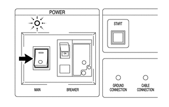
Turn the THS charger MAIN switch on.
- HINT:
-
The MAIN indicator will illuminate (green).
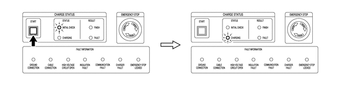
Press the START switch.
- HINT:
- ·
When the START switch is turned on, the INITIAL CHECK indicator illuminates and an initial check starts. When the initial check completes successfully, the INITIAL CHECK indicator turns off, the CHARGING indicator illuminates and charging will start at the same time.
·While the INITIAL CHECK indicator is illuminated, the insulation, 400 V output, emergency stop switch, connector connections and ground connection are inspected.
Repeat the charge cycle 3 times. When the last cycle has finished, turn the THS charger MAIN switch off.
- HINT:
- ·
Charging time using the THS charger is 10 minutes per charge cycle. The charging time when using a THS charger is a short charging time (when the battery temperature is 25°C (77°F), 10 minutes may be sufficient, if the battery temperature is 0°C (32°F), then three 10 minute charge cycles may be required) for putting the engine in a condition where it can be started (the system can enter the READY-on state). (The THS charger will automatically stop 10 minutes after charging starts.)
·There is very little chance of overcharging the HV battery during the second or third charging cycle. The SOC will not likely increase beyond the upper limit because it was low enough to prevent the engine from starting. Even if the SOC was to increase enough to exceed the limit, the hybrid vehicle control ECU will stop the Active Test to prevent overcharging.
·Cranking the engine once causes the SOC to drop approximately 1%.
·Charging the HV battery once (10 minutes) using the THS charger restores the SOC approximately 2%.
Turn the ignition switch off.
Remove the THS charger and connect the HV floor under wire (for HV Battery).
- NOTICE:
-
Make sure to disconnect the EV bonding cable last.
Disconnect SST (power inlet plug) of SST (THS charger) from the grounded AC 100 to 240 V receptacle.
Disconnect the cable to the negative (-) auxiliary battery terminal.
Remove the service plug grip.
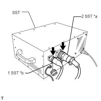
| *a | Low Voltage Cable |
| *b | High Voltage Cable |
Disconnect SST (high voltage cable) and SST (low voltage cable) from SST (THS charger) in the order shown in the illustration.
Remove the nut and disconnect SST (low voltage cable).
Disconnect SST (EV bonding cable (green cable)) from SST (THS charger).
Remove the nut and disconnect SST (EV bonding cable (green cable)).
Remove the nut and disconnect the SST (high voltage cable) terminal.
Remove the 2 nuts and HV battery upper cover panel.
Disconnect the 2 SST (high voltage cable) connectors from the HV battery junction block assembly.
Connect the shield ground to the HV battery.
Connect the 2 HV battery junction block assembly connectors.
- NOTICE:
-
Make sure that the connectors are connected securely.
Install the No. 1 hybrid battery shield sub-assembly.
Install the service plug grip.
Turn the ignition switch on (READY) and check if the engine starts.
- HINT:
-
If the engine does not start, perform the HV battery charging operation again.
Install the rear seat cushion leg sub-assembly.
Install the rear under cover.
Install the rear under side cover LH.
Install the rear under side cover RH.
Install the rear seat cushion lock hook.
Install the bench type rear seat cushion assembly.
Connect rear center seat outer belt assembly.
5. CHECK HV BATTERY AFTER HV BATTERY CHARGE
Perform the self-charging operation.
Start the engine and leave it idling with the shift lever in P until the engine stops.
- HINT:
-
When the engine stops idling, this indicates that self-charging is complete. Perform any initialization procedures required after the cable is disconnected and reconnected to the negative (-) auxiliary battery terminal.