HYBRID / BATTERY CONTROL HV BATTERY REMOVAL
CAUTION / NOTICE / HINT
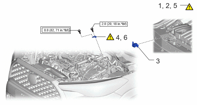
| Procedure | Part Name Code | 
|

|

|
|
|---|---|---|---|---|---|
| 1 | PRECAUTION | - | ( 202307,999999,_51,_144957,_0604247,RM100000002BTRN_02_0005,) 202307,999999,_51,_144957,_0604247,RM100000002BTRN_02_0005,)
|
- | - |
| 2 | READ VALUE USING GTS | - | (202307,999999,_51,_144957,_0604247,RM100000002BTRN_02_0004,)
|
- | - |
| 3 | SERVICE PLUG GRIP | G3834 | - | - | - |
| 4 | REMOVE CONNECTOR COVER ASSEMBLY | - | (202307,999999,_51,_144957,_0604247,RM100000002BTRN_02_0014,)
|
- | - |
| 5 | TERMINAL VOLTAGE | - | (202307,999999,_51,_144957,_0604247,RM100000002BTRN_02_0013,)
|
- | - |
| 6 | INSTALL CONNECTOR COVER ASSEMBLY | - | (202307,999999,_51,_144957,_0604247,RM100000002BTRN_02_0012,)
|
- | - |

|
Tightening torque for "Major areas involving basic vehicle performance such as moving/turning/stopping" : N*m (kgf*cm, ft.*lbf) | 
|
N*m (kgf*cm, ft.*lbf): Specified torque |

| Procedure | Part Name Code |
|
|
|
|
|---|---|---|---|---|---|
| 7 | REAR CENTER SEAT OUTER BELT ASSEMBLY | 73350C | - | - | - |
| 8 | BENCH TYPE REAR SEAT CUSHION ASSEMBLY | - | (202307,999999,_51,_144957,_0604247,RM100000002BTRN_02_0023,)
|
- | - |
| 9 | REAR SEAT CUSHION LOCK HOOK | 72693 | - | - | - |
| 10 | REAR DOOR SCUFF PLATE RH | 67917A | - | - | - |
| 11 | REAR UNDER SIDE COVER RH | 76973F | - | - | - |
| 12 | REAR DOOR SCUFF PLATE LH | 67918A | - | - | - |
| 13 | REAR UNDER SIDE COVER LH | 76974F | - | - | - |
| 14 | REAR UNDER COVER | 76971G | - | - | - |
| 15 | REAR SEAT CUSHION LEG SUB-ASSEMBLY | 71033 | - | - | - |
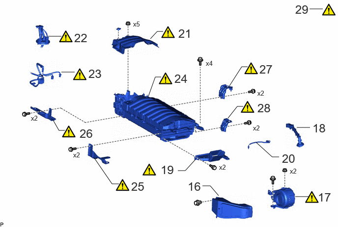
| Procedure | Part Name Code |
|
|
|
|
|---|---|---|---|---|---|
| 16 | NO. 1 EV BATTERY INTAKE DUCT | G92D1A | - | - | - |
| 17 | BATTERY COOLING BLOWER ASSEMBLY | G9230 | (202307,999999,_51,_144957,_0604247,RM100000002BTRN_02_0035,)
|
- | - |
| 18 | HYBRID BATTERY HOSE ASSEMBLY | G9290A | - | - | - |
| 19 | NO. 2 HYBRID BATTERY INTAKE DUCT | G92D2 | (202307,999999,_51,_144957,_0604247,RM100000002BTRN_02_0045,)
|
- | - |
| 20 | NO. 3 HV BATTERY PACK WIRE | G92X3 | - | - | - |
| 21 | NO. 1 HYBRID BATTERY SHIELD SUB-ASSEMBLY | G920Q | (202307,999999,_51,_144957,_0604247,RM100000002BTRN_02_0034,)
|
- | - |
| 22 | FLOOR UNDER WIRE | 821H1 | (202307,999999,_51,_144957,_0604247,RM100000002BTRN_02_0033,)
|
- | - |
| 23 | FLOOR WIRE | 82161 | (202307,999999,_51,_144957,_0604247,RM100000002BTRN_02_0032,)
|
- | - |
| 24 | HV SUPPLY BATTERY ASSEMBLY | G9510 | (202307,999999,_51,_144957,_0604247,RM100000002BTRN_02_0037,)
|
- | - |
| 25 | NO. 1 HV BATTERY CARRIER BRACKET SUB-ASSEMBLY | G920B | (202307,999999,_51,_144957,_0604247,RM100000002BTRN_02_0050,)
|
- | - |
| 26 | NO. 2 HYBRID BATTERY CARRIER BRACKET | G92K4 | (202307,999999,_51,_144957,_0604247,RM100000002BTRN_02_0049,)
|
- | - |
| 27 | NO. 3 HV BATTERY CARRIER BRACKET | G92K5 | (202307,999999,_51,_144957,_0604247,RM100000002BTRN_02_0048,)
|
- | - |
| 28 | NO. 4 HV BATTERY CARRIER BRACKET | G92K6 | (202307,999999,_51,_144957,_0604247,RM100000002BTRN_02_0047,)
|
- | - |
| 29 | RECOVERY INSPECTION | - | (202307,999999,_51,_144957,_0604247,RM100000002BTRN_02_0036,)
|
- | - |
CAUTION / NOTICE / HINT
The necessary procedures (adjustment, calibration, initialization, or registration) that must be performed after parts are removed and installed, or replaced during HV battery removal/installation are shown below.
| Replaced Part or Performed Procedure | Necessary Procedures | Effect/Inoperative Function when Necessary Procedure not Performed | Link |
|---|---|---|---|
| Replacement of HV battery | 1.
Prediagnostic battery charge 2.
Battery diagnosis 3.
Battery status info update |
HV battery status information cannot be updated | (202307,999999,_51,_144957,_0604232,RM100000002BTK8,)
|
| Replacement of hybrid battery terminal block | Perform high voltage fuse accumulated load history reset | DTCs are stored | (202307,999999,_51,_144957,_0604249,RM100000002BTRS_01_0011,)
|
- CAUTION:
- ·
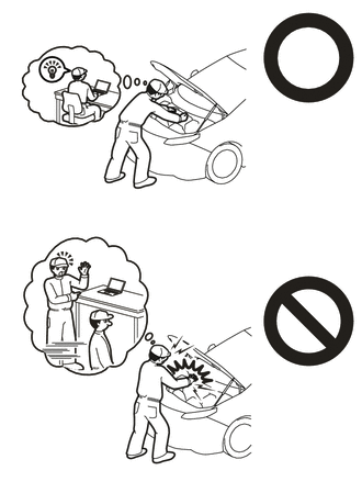
Orange wire harnesses and connectors indicate high-voltage circuits. To prevent electric shock, always follow the procedure described in the repair manual.
·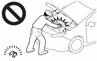
To prevent electric shock, wear insulated gloves when working on wire harnesses and components of the high voltage system.
- HINT:
- ·
When disposing of an HV battery, make sure to return it through an authorized collection agent who is capable of handling it safely. If the HV battery is returned via the manufacturer specified route, it will be returned properly and in a safe manner by an authorized collection agent.
·When the cable is disconnected / reconnected to the auxiliary battery terminal, systems temporarily stop operating. However, each system has a function that completes learning the first time the system is used.
- ·
Learning completes when vehicle is driven.
Effect/Inoperative Function When Necessary Procedures are not Performed Necessary Procedures Link Front Camera System Drive the vehicle straight ahead at 15 km/h (10 mph) or more for 1 second or more. ( 202307,999999,_95,_112293,_0586709,RM100000002BSVY,)
·Learning completes when vehicle is operated normally
Effect/Inoperative Function When Necessary Procedures are not Performed Necessary Procedures Link Power door lock control system
·Back door opener
Perform door unlock operation with door control switch or electrical key transmitter sub-assembly switch. ( 202201,999999,_58,_115226,_0510939,RM1000000020BSY,)
Power back door system Fully close the back door by hand.
- HINT:
-
Initialization is not necessary if the above procedures are performed while the back door is closed.
( 202201,999999,_59,_113746,_0504731,RM100000001ZJKP,)
Air conditioning system After the ignition switch is turned to ON, the servo motor standard position is recognized. -
PROCEDURE

 1. PRECAUTION
- NOTICE:
- ·
After turning the ignition switch off, waiting time may be required before disconnecting the cable from the negative (-) auxiliary battery terminal.
·If the HV battery has been struck or dropped, replace it.
·When connecting a connector to the HV battery, confirm that the connector is securely connected through the following:
- Push the connector until a click sound is heard.
- Visually check and confirm that the connector is securely connected by pulling on it.
·Make sure to insulate the high-voltage connectors and terminals of the HV battery with insulating tape after removing it.
If the HV battery stored without insulating the connectors and terminals, electric shock or fire may result.
·When performing repairs around the HV battery, such as using a tap, do not allow metal shavings to enter the HV battery.
·Do not touch any high voltage wire harnesses, connectors or parts with bare hands.
·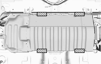
Hold the areas shown in the illustration and lift the HV battery.
·Do not allow foreign matter, such as grease or oil, to adhere to the bolts or nuts of the HV battery.
·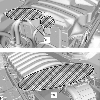 0.865,0.615 1.521,1.24 1.521,1.24 1.469,0.844 true 2.021,3.198 2.354,2.885 true 1.5,1.281 1.708,1.479 0.208,0.198 10 true *a 1.76,3.177 1.969,3.375 0.208,0.198 10 true *a
*a Opening
Do not put your hands into the openings of the HV battery.
·When removing/installing/moving the HV battery assembly, make sure not to tilt it more than 80°.
·Do not climb on top of or stand on the HV battery.
·Do not allow any foreign matter or water to enter the HV battery.
·If any bolts, nuts or clips are dropped into the HV battery, make sure to remove them.
2. READ VALUE USING GTS
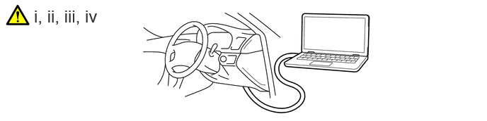
Connect the GTS to the DLC3.
Turn the ignition switch on (IG).
Enter the following menus: Powertrain / HV Battery / Data List / Hybrid/EV Battery Temperature 1 to 6.
- Powertrain > HV Battery > Data List
-
Tester Display Hybrid/EV Battery Temperature 1 Hybrid/EV Battery Temperature 2 Hybrid/EV Battery Temperature 3 Hybrid/EV Battery Temperature 4 Hybrid/EV Battery Temperature 5 Hybrid/EV Battery Temperature 6 - 50003 398 62,63,64,65,66,67
Read the Data List.
- NOTICE:
-
If any of the temperatures listed in "Hybrid/EV Battery Temperature 1 to 6" are 50°C or more, leave the vehicle until the temperature drops to less than 50°C.
G3834
3.REMOVE SERVICE PLUG GRIP
4.REMOVE CONNECTOR COVER ASSEMBLY
5.CHECK TERMINAL VOLTAGE
6.INSTALL CONNECTOR COVER ASSEMBLY
|
|
|

| *a | Bolt (A) | *b | Bolt (B) |
Using a T30 "TORX" socket wrench, install the connector cover assembly to the inverter with converter assembly with the bolt (A).
- Torque:
- 2.0 N*m (20 kgf*cm, 18 in.*lbf)
- NOTICE:
-
Do not touch the waterproof seal of the connector cover assembly.
Install the bolt (B).
- Torque:
- 8.0 N*m (82 kgf*cm, 71 in.*lbf)
73350C
7.DISCONNECT REAR CENTER SEAT OUTER BELT ASSEMBLY
8.REMOVE BENCH TYPE REAR SEAT CUSHION ASSEMBLY
72693
9.REMOVE REAR SEAT CUSHION LOCK HOOK
67917A
10.REMOVE REAR DOOR SCUFF PLATE RH
76973E
11.REMOVE REAR UNDER SIDE COVER RH
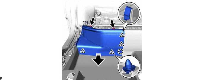

|
Remove in this Direction | - | - |
67918A
12.REMOVE REAR DOOR SCUFF PLATE LH
Use the same procedure as for the RH side.
76974E
13.REMOVE REAR UNDER SIDE COVER LH
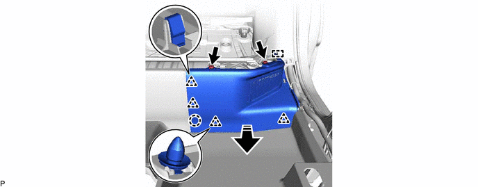
|
|
Remove in this Direction | - | - |
76971F
14.REMOVE REAR UNDER COVER

71033
15.REMOVE REAR SEAT CUSHION LEG SUB-ASSEMBLY

G92D1A
16.REMOVE NO. 1 EV BATTERY INTAKE DUCT
G9230
17.REMOVE BATTERY COOLING BLOWER ASSEMBLY
G9290A
18.REMOVE HYBRID BATTERY HOSE ASSEMBLY

G92D2
19.REMOVE NO. 2 HYBRID BATTERY INTAKE DUCT
|
|
|

G92X3
20.REMOVE NO. 3 HV BATTERY PACK WIRE

G920Q
21.REMOVE NO. 1 HYBRID BATTERY SHIELD SUB-ASSEMBLY
|
|
|
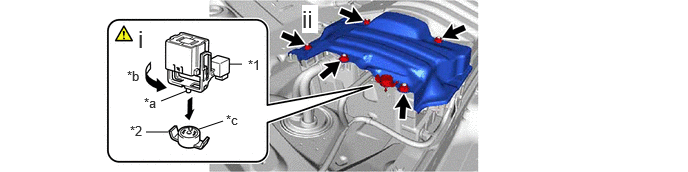
| *1 | Service Plug Grip | *2 | Battery Cover Lock Striker |
| *a | Projection | *b | Turn |
| *c | Button | - | - |
Using the service plug grip, remove the battery cover lock striker.
- HINT:
-
Insert the projection of the service plug grip and turn the button of the battery cover lock striker counterclockwise to release the lock.
Remove the 5 nuts and HV battery upper cover panel from the HV battery.
821H1
22.DISCONNECT FLOOR UNDER WIRE
|
|
|

| *a | Shield Ground | - | - |
Disconnect the 2 HV battery junction block assembly connectors.
Disconnect the shield ground from the HV battery.
82161
23.DISCONNECT FLOOR WIRE
|
|
|

G9510
24.REMOVE HV SUPPLY BATTERY ASSEMBLY
|
|
|

G920B
25.REMOVE NO. 1 HV BATTERY CARRIER BRACKET SUB-ASSEMBLY
|
|
|

G92K4
26.REMOVE NO. 2 HYBRID BATTERY CARRIER BRACKET
|
|
|

G92K5
27.REMOVE NO. 3 HV BATTERY CARRIER BRACKET
|
|
|

G92K6
28.REMOVE NO. 4 HV BATTERY CARRIER BRACKET
|
|
|

29.PERFORM RECOVERY INSPECTION
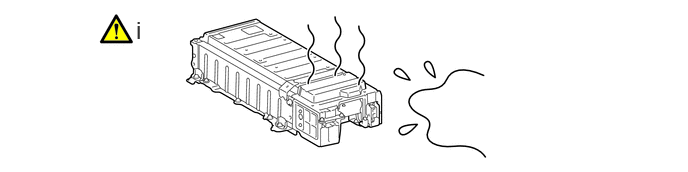
Before returning the HV battery, make sure to perform a recovery inspection.