HYBRID / BATTERY CONTROL MOTOR GENERATOR CONTROL SYSTEM P0A3611 Generator Temperature Sensor Circuit Short to Ground P0A3615 Generator Temperature Sensor Circuit Short to Auxiliary Battery or Open
DTC SUMMARY
MALFUNCTION DESCRIPTION
These DTCs are stored when the generator temperature sensor output is abnormal. The cause of this malfunction may be one of the following:
Motor generator control ECU (MG ECU) internal malfunction
Internal generator temperature sensor malfunction
Open or short in generator temperature sensor
The connectors are not connected properly
Foreign matter or water on the connector terminals
Open or short in wire harness
- HINT:
-
If any of these DTCs are stored, the generator temperature sensor is malfunctioning and the self-protection function may not operate. Therefore under certain high load driving condition, the temperature of the generator (MG1) becomes high. If the self-protection function does not operate, the generator (MG1) may malfunction and cause the vehicle to enter fail-safe mode.
DESCRIPTION
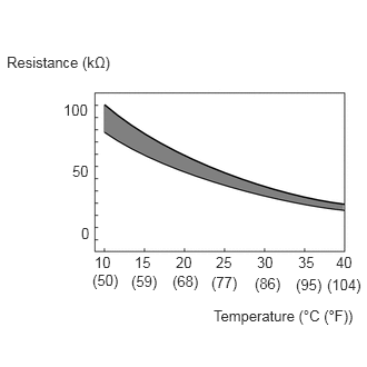
The resistance of the thermistor built into the generator temperature sensor changes in accordance with changes in generator (MG1) temperature. The lower the generator (MG1) temperature, the higher the thermistor resistance. Conversely, the higher the generator (MG1) temperature, the lower the resistance.
| DTC No. | Detection Item | DTC Detection Condition | Trouble Area | MIL | Warning Indicate | Note |
|---|---|---|---|---|---|---|
| P0A3611 | Generator Temperature Sensor Circuit Short to Ground | Short to ground in the generator temperature sensor circuit
(1 trip detection logic) |
·
Wire harness or connector ·
Inverter with converter assembly ·
Generator temperature sensor (Hybrid vehicle transaxle assembly) |
Comes on | Master Warning:
Comes on |
SAE Code:
P0A38 |
| P0A3615 | Generator Temperature Sensor Circuit Short to Auxiliary Battery or Open | Open or short to +B in the generator temperature sensor circuit
(1 trip detection logic) |
·
Wire harness or connector ·
Inverter with converter assembly ·
Generator temperature sensor (Hybrid vehicle transaxle assembly) |
Comes on | Master Warning:
Comes on |
SAE Code:
P0A39 |
- HINT:
-
After confirming that DTC P0A3611 or P0A3615 is output, use the GTS to check "Generator Temperature" in the Data List.
Displayed Temperature Malfunction -40°C (-40°F) Open circuit or short to +B 215°C (419°F) Short to ground
MONITOR DESCRIPTION
If the motor generator control ECU detects a malfunction of the generator temperature sensor, it will illuminate the MIL and store a DTC.
MONITOR STRATEGY
| Related DTCs | P0A38 (INF P0A3611): Generator Temperature Sensor Circuit Low
P0A39 (INF P0A3615): Generator Temperature Sensor Circuit High |
| Required sensors/components | Generator temperature sensor |
| Frequency of operation | Continuous |
| Duration | TMC's intellectual property |
| MIL operation | 1 driving cycle |
| Sequence of operation | None |
TYPICAL ENABLING CONDITIONS
| The monitor will run whenever the following DTCs are not stored | TMC's intellectual property |
| Other conditions belong to TMC's intellectual property | - |
TYPICAL MALFUNCTION THRESHOLDS
| TMC's intellectual property | - |
COMPONENT OPERATING RANGE
| Motor generator control ECU | DTC P0A38 (INF P0A3611) is not detected
DTC P0A39 (INF P0A3615) is not detected |
CONFIRMATION DRIVING PATTERN
- HINT:
- ·
After repair has been completed, clear the DTC and then check that the vehicle has returned to normal by performing the following All Readiness check procedure.
·When clearing the permanent DTCs, refer to the "CLEAR PERMANENT DTC" procedure.
Connect the GTS to the DLC3.
Turn the ignition switch to ON and turn the GTS on.
Clear the DTCs (even if no DTCs are stored, perform the clear DTC procedure).
Turn the ignition switch off and wait for 2 minutes or more.
Turn the ignition switch to ON and turn the GTS on.
With ignition switch ON and wait for 5 seconds or more. [*1]
- HINT:
-
[*1]: Normal judgment procedure.
-
The normal judgment procedure is used to complete DTC judgment and also used when clearing permanent DTCs.
Enter the following menus: Powertrain / Motor Generator / Utility / All Readiness.
Check the DTC judgment result.
- HINT:
- ·
If the judgment result shows NORMAL, the system is normal.
·If the judgment result shows ABNORMAL, the system has a malfunction.
·If the judgment result shows INCOMPLETE, perform the normal judgment procedure again.
WIRING DIAGRAM
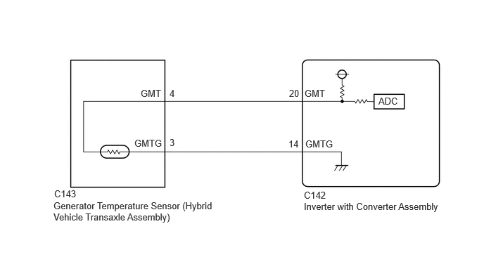
CAUTION / NOTICE / HINT
- CAUTION:
-
Refer to the precautions before inspecting high voltage circuit.
- NOTICE:
- ·
After the ignition switch is turned off, there may be a waiting time before disconnecting the negative (-) auxiliary battery terminal.
·When disconnecting and reconnecting the auxiliary battery.
- HINT:
-
When disconnecting and reconnecting the auxiliary battery, there is an automatic learning function that completes learning when the respective system is used.
PROCEDURE
- Result:
Result Proceed to OK A NG (The connector is not connected securely.) B NG (The terminals are not making secure contact or are deformed, or water or foreign matter exists in the connector.) C
A
B
C
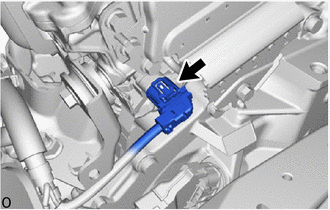
Check the connection condition of the generator temperature sensor connector and the contact pressure of each terminal. Check the terminals for deformation, and check the connector for water ingress and foreign matter.
- OK:
- The connector is connected securely.
- The terminals are not deformed and are connected securely.
- No water or foreign matter in the connector.
- Result:
Result Proceed to OK A NG (The connector is not connected securely.) B NG (The terminals are not making secure contact or are deformed, or water or foreign matter exists in the connector.) C
A
B
C
Read the Data List.
- Powertrain > Motor Generator > Data List
-
Tester Display Generator Temperature - 50003 395 277
- Result:
Result Proceed to -40°C (-40°F) A Same as actual temperature B
Turn the ignition switch off.
A
B
Disconnect the generator temperature sensor connector.
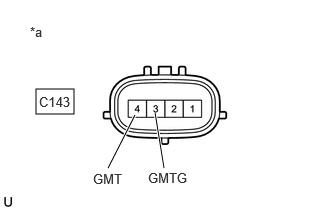
| *a | Component without harness connected
(Generator Temperature Sensor (Hybrid Vehicle Transaxle Assembly)) |
Measure the resistance according to the value(s) in the table below.
- Standard Resistance:
Tester Connection Condition Specified Condition C143-4 (GMT) - C143-3 (GMTG) Ignition switch off 0.3 to 2000 kΩ
Reconnect the generator temperature sensor connector.
- Result:
Proceed to OK NG
OK
NG
Disconnect the generator temperature sensor connector.
Disconnect the inverter with converter assembly connector.
Measure the resistance according to the value(s) in the table below.
- Standard Resistance (Check for Open):
Tester Connection Condition Specified Condition C143-4 (GMT) - C142-20 (GMT) Ignition switch off Below 1 Ω C143-3 (GMTG) - C142-14 (GMTG) Ignition switch off Below 1 Ω
- Standard Resistance (Check for Short):
Tester Connection Condition Specified Condition C143-4 (GMT) or C142-20 (GMT) - Body ground and other terminals Ignition switch off 10 kΩ or higher C143-3 (GMTG) or C142-14 (GMTG) - Body ground and other terminals Ignition switch off 10 kΩ or higher
Reconnect the inverter with converter assembly connector.
Reconnect the generator temperature sensor connector.
- Result:
Proceed to OK NG
OK
NG