HYBRID / BATTERY CONTROL MOTOR GENERATOR CONTROL SYSTEM P0A9000 Drive Motor "A" Performance
DTC SUMMARY
MALFUNCTION DESCRIPTION
This DTC indicates that magnetic force deterioration of the permanent magnet located in the rotor inside the motor (MG2) has been detected. The cause of this malfunction may be one of the following:
| Area | Main Malfunction Description |
|---|---|
| Inverter | Inverter with converter assembly internal circuit malfunction |
| Hybrid vehicle transaxle assembly | ·
Motor (MG2) malfunction (entry of foreign matter, etc.) ·
Motor (MG2) permanent magnet magnetic force deterioration ·
Open or short circuit in the motor coils |
| Inverter low-voltage circuit | The connectors are not connected properly |
| Motor cable (for MG2) | ·
Defective motor cable (for MG2) connection condition ·
Open circuit or poor insulation in motor cable (for MG2) |
| Hybrid vehicle control ECU | Hybrid vehicle control ECU internal circuit malfunction |
DESCRIPTION
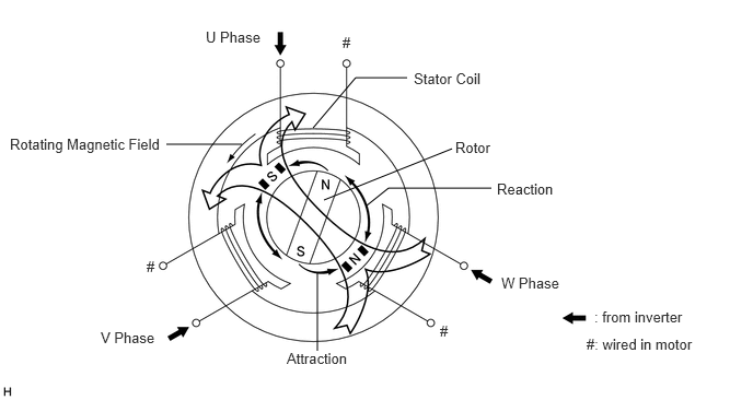
When three-phase alternating current flows through the three-phase windings of the stator coil, a rotating magnetic field is generated in the motor (MG2). The system controls the rotation of the magnetic field in accordance with the rotating position and speed of the rotor. As a result, the permanent magnets provided in the rotor are pulled in the direction of rotation, generating torque. The generated torque is almost proportional to the amount of current. The system controls motor speed by regulating the frequency of the alternating current. Furthermore, the system properly controls the rotating magnetic field and the angle of the rotor magnets in order to generate high torque in an efficient manner, even at high speeds.
| DTC No. | Detection Item | DTC Detection Condition | Trouble Area | MIL | Warning Indicate | Note |
|---|---|---|---|---|---|---|
| P0A9000 | Drive Motor "A" Performance | Motor magnetic force deterioration:
Decrease in the magnetic force of the motor (MG2) is detected. (1 trip detection logic) |
·
Hybrid vehicle transaxle assembly ·
Motor cable ·
Inverter with converter assembly ·
Wire harness or connector ·
Hybrid vehicle control ECU |
Comes on | Master Warning:
Comes on |
SAE Code:
P0A90 |
MONITOR DESCRIPTION
The motor generator control ECU monitors the motor. If the motor generator control ECU detects a reduction in the magnetic force of the motor, it interprets this as a motor malfunction and the ECU will illuminate the MIL and store a DTC.
MONITOR STRATEGY
| Related DTCs | P0A90 (INF P0A9000): Degauss / Same phase short circuit |
| Required sensors/components | Motor (MG2), inverter, motor resolver |
| Frequency of operation | Continuous |
| Duration | TMC's intellectual property |
| MIL operation | 1 driving cycle |
| Sequence of operation | None |
TYPICAL ENABLING CONDITIONS
| The monitor will run whenever the following DTCs are not stored | TMC's intellectual property |
| Other conditions belong to TMC's intellectual property | - |
TYPICAL MALFUNCTION THRESHOLDS
| TMC's intellectual property | - |
COMPONENT OPERATING RANGE
| Motor generator control ECU | P0A90 (INF P0A9000) is not detected |
CONFIRMATION DRIVING PATTERN
- HINT:
- ·
After repair has been completed, clear the DTC and then check that the vehicle has returned to normal by performing the following All Readiness check procedure.
·When clearing the permanent DTCs, refer to the "CLEAR PERMANENT DTC" procedure.
Clear the DTCs (even if no DTCs are stored, perform the clear DTC procedure).
Turn the ignition switch off and wait for 2 minutes or more.
Turn the ignition switch to ON (READY). [*1]
Drive the vehicle until the cumulative traveling time driving at a vehicle speed of 40 km/h (25 mph) or more is a few minutes. (It is not necessary to drive continuously at 40 km/h (25 mph) or more.) [*2]
- HINT:
-
[*1] to [*2]: Normal judgment procedure.
-
The normal judgment procedure is used to complete DTC judgment and also used when clearing permanent DTCs.
Enter the following menus: Powertrain / Motor Generator / Utility / All Readiness.
Check the DTC judgment result.
- HINT:
- ·
If the judgment result shows NORMAL, the system is normal.
·If the judgment result shows ABNORMAL, the system has a malfunction.
·If the judgment result shows INCOMPLETE, perform the normal judgment procedure again.
WIRING DIAGRAM
Refer to the wiring diagram for the Motor High-voltage Circuit.
Refer to the wiring diagram for the Shut Down Signal Circuit.
CAUTION / NOTICE / HINT
- CAUTION:
-
Refer to the precautions before inspecting high voltage circuit.
- NOTICE:
- ·
After the ignition switch is turned off, there may be a waiting time before disconnecting the negative (-) auxiliary battery terminal.
·When disconnecting and reconnecting the auxiliary battery.
- HINT:
-
When disconnecting and reconnecting the auxiliary battery, there is an automatic learning function that completes learning when the respective system is used.
- HINT:
P0A9000 may be output as a result of the malfunction indicated by the DTCs in table below.
(a)The chart above is listed in inspection order of priority.
(b)Check DTCs that are output at the same time by following the listed order. (The main cause of the malfunction can be determined without performing unnecessary inspections.)
| Malfunction Content | System | Relevant DTC | |
|---|---|---|---|
| Insulation malfunction | Hybrid control system | P1C7C49 | Hybrid/EV Battery Voltage System Isolation (A/C Area) Internal Electronic Failure |
| P1C7D49 | Hybrid/EV Battery Voltage System Isolation (Hybrid/EV Battery Area) Internal Electronic Failure | ||
| P1C7E49 | Hybrid/EV Battery Voltage System Isolation (Transaxle Area) Internal Electronic Failure | ||
| P1C7F49 | Hybrid/EV Battery Voltage System Isolation (Direct Current Area) Internal Electronic Failure | ||
| P1C8049 | Hybrid/EV Battery Voltage System Isolation (Rear Motor Area) Internal Electronic Failure | ||
| System main relay or high voltage circuit malfunction | Hybrid control system | P0AD911 | Hybrid/EV Battery Positive Contactor Circuit Short to Ground |
| P0AD915 | Hybrid/EV Battery Positive Contactor Circuit Short to Auxiliary Battery or Open | ||
| P0ADD11 | Hybrid/EV Battery Negative Contactor Circuit Short to Ground | ||
| P0ADD15 | Hybrid/EV Battery Negative Contactor Circuit Short to Auxiliary Battery or Open | ||
| P1C8449 | High Voltage Power Resource Circuit Short during Ready ON | ||
| Malfunction Content | System | Relevant DTC | |
|---|---|---|---|
| Microcomputer malfunction | Motor generator control system | P0A1A47 | Generator Control Module Watchdog / Safety MC Failure |
| P0A1A49 | Generator Control Module Internal Electronic Failure | ||
| P0A1B1F | Generator Control Module Circuit Intermittent | ||
| P0A1B47 | Drive Motor "A" Control Module Watchdog / Safety MC Failure | ||
| P0A1C49 | Drive Motor "B" Control Module Internal Electronic Failure | ||
| P1C2A1C | Generator A/D Converter Circuit Circuit Voltage Out of Range | ||
| P1C2A49 | Generator A/D Converter Circuit Internal Electronic Failure | ||
| P1C2A71 | Generator A/D Converter Circuit Actuator Stuck | ||
| P1C2B1C | Drive Motor "A" Control Module A/D Converter Circuit Voltage Out of Range | ||
| P1C2B49 | Drive Motor "A" Control Module A/D Converter Circuit Internal Electronic Failure | ||
| P1C2B71 | Drive Motor "A" Control Module A/D Converter Circuit Actuator Stuck | ||
| P1C2C1C | Drive Motor "B" Control Module AD Converter Circuit Voltage Out of Range | ||
| P1C2C49 | Drive Motor "B" Control Module AD Converter Internal Electronic Failure | ||
| P1C2C71 | Drive Motor "B" Control Module A/D Converter Circuit Actuator Stuck | ||
| P310A83 | Communication Error from Drive Motor "B" to Drive Motor "A" Value of Signal Protection Calculation Incorrect | ||
| P310A86 | Communication Error from Drive Motor "B" to Drive Motor "A" Signal (Some Circuit Quantity, Reported via Serial Data) Invalid | ||
| P310A87 | Communication Error from Drive Motor "B" to Drive Motor "A" Missing Message | ||
| P310B83 | Communication Error from Drive Motor "A" to Drive Motor "B" Value of Signal Protection Calculation Incorrect | ||
| P310B86 | Communication Error from Drive Motor "A" to Drive Motor "B" Signal (Some Circuit Quantity, Reported via Serial Data) Invalid | ||
| P310B87 | Communication Error from Drive Motor "A" to Drive Motor "B" Missing Message | ||
| P313383 | Communication Error from Generator to Drive Motor "A" Value of Signal Protection Calculation Incorrect | ||
| P313386 | Communication Error from Generator to Drive Motor "A" Signal Invalid | ||
| P313387 | Communication Error from Generator to Drive Motor "A" Missing Message | ||
| P313483 | Communication Error from Drive Motor "A" to Generator Value of Signal Protection Calculation Incorrect | ||
| P313486 | Communication Error from Drive Motor "A" to Generator Signal Invalid | ||
| P313487 | Communication Error from Drive Motor "A" to Generator Missing Message | ||
| P32BF83 | Lost Communication between Drive Motor "A" and "B" (Drive Motor "A") Value of Signal Protection Calculation Incorrect | ||
| P32BF86 | Lost Communication between Drive Motor "A" and "B" (Drive Motor "A") Signal (Some Circuit Quantity, Reported via Serial Data) Invalid | ||
| P32BF87 | Lost Communication between Drive Motor "A" and "B" (Drive Motor "A") Missing Message | ||
| P32CF83 | Lost Communication between Drive Motor "A" and "B" (Drive Motor "B") Value of Signal Protection Calculation Incorrect | ||
| P32CF86 | Lost Communication between Drive Motor "A" and "B" (Drive Motor "B") Signal (Some Circuit Quantity, Reported via Serial Data) Invalid | ||
| P32CF87 | Lost Communication between Drive Motor "A" and "B" (Drive Motor "B") Missing Message | ||
| Hybrid control system | P0A1B49 | Drive Motor "A" Control Module Internal Electronic Failure | |
| Power source circuit malfunction | Motor generator control system | P06B01C | Generator Control Module Position Sensor REF Power Source Circuit Voltage Out of Range |
| P06B31C | Drive Motor "B" Control Module Position Sensor REF Power Source Circuit Voltage Out of Range | ||
| P06D61C | Generator Control Module Offset Power Circuit Voltage Out of Range | ||
| P19F81C | Generator Control Module Offset Power Circuit Voltage Out of Range | ||
| P19F91C | Drive Motor "B" Control Module Offset Power Circuit Voltage Out of Range | ||
| P26DF1C | Generator Control Module Position Sensor REF Power Source Circuit Voltage Out of Range | ||
| Sensor and actuator circuit malfunction | Motor generator control system | P0A3F16 | Drive Motor "A" Position Sensor Circuit Voltage Below Threshold |
| P0A3F21 | Drive Motor "A" Position Sensor Signal Amplitude < Minimum | ||
| P0A3F22 | Drive Motor "A" Position Sensor Signal Amplitude > Maximum | ||
| P0A4516 | Drive Motor "B" Position Sensor Circuit Voltage Below Threshold | ||
| P0A4521 | Drive Motor "B" Position Sensor Signal Amplitude < Minimum | ||
| P0A4522 | Drive Motor "B" Position Sensor Signal Amplitude > Maximum | ||
| P0A4B16 | Generator Position Sensor Circuit Voltage Below Threshold | ||
| P0A4B21 | Generator Position Sensor Signal Amplitude < Minimum | ||
| P0A4B22 | Generator Position Sensor Signal Amplitude > Maximum | ||
| P0A6012 | Drive Motor "A" Phase V Current (High Resolution) Circuit Short to Battery | ||
| P0A6014 | Drive Motor "A" Phase V Current (High Resolution) Circuit Short to Ground or Open | ||
| P0A601C | Drive Motor "A" Phase V Current (High Resolution) Circuit Voltage Out of Range | ||
| P0A6312 | Drive Motor "A" Phase W Current (High Resolution) Circuit Short to Battery | ||
| P0A6314 | Drive Motor "A" Phase W Current (High Resolution) Circuit Short to Ground or Open | ||
| P0A631C | Drive Motor "A" Phase W Current (High Resolution) Circuit Voltage Out of Range | ||
| P0A6912 | Drive Motor "B" Phase V Current(High Resolution) Circuit Short to Battery | ||
| P0A6914 | Drive Motor "B" Phase V Current(High Resolution) Circuit Short to Ground or Open | ||
| P0A691C | Drive Motor "B" Phase V Current(High Resolution) Circuit Voltage Out of Range | ||
| P0A6C12 | Drive Motor "B" Phase W Current(High Resolution) Circuit Short to Battery | ||
| P0A6C14 | Drive Motor "B" Phase W Current(High Resolution) Circuit Short to Ground or Open | ||
| P0A6C1C | Drive Motor "B" Phase W Current(High Resolution) Circuit Voltage Out of Range | ||
| P0BE512 | Drive Motor "A" Phase U Current Sensor Circuit Short to Battery | ||
| P0BE514 | Drive Motor "A" Phase U Current Sensor Circuit Short to Ground or Open | ||
| P0BE528 | Drive Motor "A" Phase U Current Sensor Signal Bias Level Out of Range / Zero Adjustment Failure | ||
| P0BE912 | Drive Motor "A" Phase V Current Sensor Circuit Short to Battery | ||
| P0BE914 | Drive Motor "A" Phase V Current Sensor Circuit Short to Ground or Open | ||
| P0BE928 | Drive Motor "A" Phase V Current Sensor Signal Bias Level Out of Range / Zero Adjustment Failure | ||
| P0BED12 | Drive Motor "A" Phase W Current Sensor Circuit Short to Battery | ||
| P0BED14 | Drive Motor "A" Phase W Current Sensor Circuit Short to Ground or Open | ||
| P0BED28 | Drive Motor "A" Phase W Current Sensor Signal Bias Level Out of Range / Zero Adjustment Failure | ||
| P0BF112 | Drive Motor "B" Phase U Current Sensor Circuit Short to Battery | ||
| P0BF114 | Drive Motor "B" Phase U Current Sensor Circuit Short to Ground or Open | ||
| P0BF128 | Drive Motor "B" Phase U Current Sensor Signal Bias Level Out of Range / Zero Adjustment Failure | ||
| P0BF512 | Drive Motor "B" Phase V Current Sensor Circuit Short to Battery | ||
| P0BF514 | Drive Motor "B" Phase V Current Sensor Circuit Short to Ground or Open | ||
| P0BF528 | Drive Motor "B" Phase V Current Sensor Signal Bias Level Out of Range / Zero Adjustment Failure | ||
| P0BF912 | Drive Motor "B" Phase W Current Sensor Circuit Short to Battery | ||
| P0BF914 | Drive Motor "B" Phase W Current Sensor Circuit Short to Ground or Open | ||
| P0BF928 | Drive Motor "B" Phase W Current Sensor Signal Bias Level Out of Range / Zero Adjustment Failure | ||
| P0BFD62 | Drive Motor "A" Phase U-V-W Current Sensor Signal Compare Failure | ||
| P0BFE62 | Drive Motor "B" Phase U-V-W Current Sensor Signal Compare Failure | ||
| P0C5013 | Drive Motor "A" Position Sensor Circuit "A" Circuit Open | ||
| P0C5016 | Drive Motor "A" Position Sensor Circuit "A" Circuit Voltage Below Threshold | ||
| P0C5017 | Drive Motor "A" Position Sensor Circuit "A" Circuit Voltage Above Threshold | ||
| P0C5513 | Drive Motor "B" Position Sensor Circuit "A" Circuit Open | ||
| P0C5516 | Drive Motor "B" Position Sensor Circuit "A" Circuit Voltage Below Threshold | ||
| P0C5517 | Drive Motor "B" Position Sensor Circuit "A" Circuit Voltage Above Threshold | ||
| P0C5A13 | Drive Motor "A" Position Sensor Circuit "B" Circuit Open | ||
| P0C5A16 | Drive Motor "A" Position Sensor Circuit "B" Circuit Voltage Below Threshold | ||
| P0C5A17 | Drive Motor "A" Position Sensor Circuit "B" Circuit Voltage Above Threshold | ||
| P0C5F13 | Drive Motor "B" Position Sensor Circuit "B" Circuit Open | ||
| P0C5F16 | Drive Motor "B" Position Sensor Circuit "B" Circuit Voltage Below Threshold | ||
| P0C5F17 | Drive Motor "B" Position Sensor Circuit "B" Circuit Voltage Above Threshold | ||
| P0C6413 | Generator Position Sensor Circuit "A" Circuit Open | ||
| P0C6416 | Generator Position Sensor Circuit "A" Circuit Voltage Below Threshold | ||
| P0C6417 | Generator Position Sensor Circuit "A" Circuit Voltage Above Threshold | ||
| P0C6913 | Generator Position Sensor Circuit "B" Circuit Open | ||
| P0C6916 | Generator Position Sensor Circuit "B" Circuit Voltage Below Threshold | ||
| P0C6917 | Generator Position Sensor Circuit "B" Circuit Voltage Above Threshold | ||
| P0D2D16 | Drive Motor "A" Inverter Voltage Sensor (VH) Circuit Voltage Below Threshold | ||
| P0D2D17 | Drive Motor "A" Inverter Voltage Sensor (VH) Circuit Voltage Above Threshold | ||
| P0DFA62 | Generator Phase U-V-W Current Sensor Signal Compare Failure | ||
| P0E0012 | Generator Phase U Current Sensor Circuit Short to Battery | ||
| P0E0014 | Generator Phase U Current Sensor Circuit Short to Ground or Open | ||
| P0E0028 | Generator Phase U Current Sensor Signal Bias Level Out of Range / Zero Adjustment Failure | ||
| P0E0412 | Generator Phase V Current Sensor Circuit Short to Battery | ||
| P0E0414 | Generator Phase V Current Sensor Circuit Short to Ground or Open | ||
| P0E0428 | Generator Phase V Current Sensor Signal Bias Level Out of Range / Zero Adjustment Failure | ||
| P0E0812 | Generator Phase W Current Sensor Circuit Short to Battery | ||
| P0E0814 | Generator Phase W Current Sensor Circuit Short to Ground or Open | ||
| P0E0828 | Generator Phase W Current Sensor Signal Bias Level Out of Range / Zero Adjustment Failure | ||
| P0E3116 | DC/DC Converter Voltage Sensor "A" (VL) Circuit Voltage Below Threshold | ||
| P0E3117 | DC/DC Converter Voltage Sensor "A" (VL) Circuit Voltage Above Threshold | ||
| P0E5111 | DC/DC Converter Current Sensor Circuit Short to Ground | ||
| P0E5115 | DC/DC Converter Current Sensor Circuit Short to Battery or Open | ||
| P0E5128 | DC/DC Converter Current Sensor Signal Bias Level Out of Range / Zero Adjustment Failure | ||
| P0E512A | DC/DC Converter Current Sensor Signal Stuck In Range | ||
| P1CAC49 | Generator Position Sensor Internal Electronic Failure | ||
| P1CAD49 | Drive Motor "A" Position Sensor Internal Electronic Failure | ||
| P1CAE49 | Drive Motor "B" Position Sensor Internal Electronic Failure | ||
| P1CAF38 | Generator Position Sensor REF Signal Cycle Malfunction Signal Frequency Incorrect | ||
| P1CB038 | Drive Motor "A" Position Sensor REF Signal Frequency Incorrect | ||
| P1CB138 | Drive Motor "B" Position Sensor REF Signal Frequency Incorrect | ||
| P1CFF62 | Hybrid/EV Battery Current/DC/DC Converte rCurrent Signal Compare Failure | ||
| Hybrid control system | P0C7600 | Hybrid/EV Battery System Discharge Time Too Long | |
| P0D2D1C | Drive Motor "A" Inverter Voltage Sensor Voltage Out of Range | ||
| P0E311C | Boosting Converter Voltage Sensor "A" Voltage Out of Range | ||
| P1C2D62 | Hybrid/EV Battery "A" Voltage Sensor/Boosting Converter Voltage Sensor "A" Signal Compare Failure | ||
| System malfunction | Motor generator control system | P0A7873 | Drive Motor "A" Inverter Actuator Stuck Closed |
| P0A7973 | Drive Motor "B" Inverter Actuator Stuck Closed | ||
| P0A7A73 | Generator Inverter Actuator Stuck Closed | ||
| P0C1900 | Drive Motor "A" Execution Torque Performance | ||
PROCEDURE
Read the diagnosis related information and freeze frame data of DTC P0A9000.
- Powertrain > Motor Generator > Utility
-
Tester Display Diagnosis Related Information - 50005 395 56
- Powertrain > Motor Generator > Trouble Codes
- 50001 395
- Result:
Result Proceed to DTC U11B300 or U11B387 is listed in Diagnosis Related Information. A DTC U11B300 or U11B387 is not listed in Diagnosis Related Information and the value of freeze frame data item Emergency Shutdown Signal is ON. B Other than above C
Turn the ignition switch off.
A
B
C
Clear the DTCs.
- Powertrain > Motor Generator > Clear DTCs
- 50002 395
Turn the ignition switch to ON (READY) with the shift lever in P.
Turn the air conditioning system on and wait for 1 minute with the engine stopped.
- HINT:
-
If the engine starts before 1 minute has elapsed, wait until it stops and then perform this step again.
Check for DTCs.
- Powertrain > Motor Generator > Trouble Codes
- 50001 395
- Result:
Result Proceed to P0A9000 or P0BFF1D is output, or DTC is not output. A DTCs other than P0A9000 and P0BFF1D are also output. B
Turn the ignition switch off.
A
B
Clear the DTCs.
- Powertrain > Motor Generator > Clear DTCs
- 50002 395
Turn the ignition switch to ON (READY).
Move the shift lever to D.
Depress the accelerator pedal halfway or more and accelerate the vehicle to 20 km/h (12.4 mph).
- CAUTION:
-
When performing the confirmation driving pattern, obey all speed limits and traffic laws.
Check for DTCs.
- Powertrain > Motor Generator > Trouble Codes
- 50001 395
- Result:
Result Proceed to P0A9000 or P0BFF1D is output, or DTC is not output. A DTCs other than P0A9000 and P0BFF1D are also output. B
Turn the ignition switch off.
A
B
- Result:
Result Proceed to OK A NG (The connector is not connected securely.) B NG (The terminals are not making secure contact or are deformed, or water or foreign matter exists in the connector.) C
A
B
C
- Result:
Proceed to NEXT
NEXT
- HINT:
-
If the "Motor High-voltage Circuit" inspection results are normal, perform the next step.
- Result:
Proceed to NEXT
NEXT