PB10 HYBRID TRANSMISSION / TRANSAXLE MOTOR CABLE REMOVAL
CAUTION / NOTICE / HINT
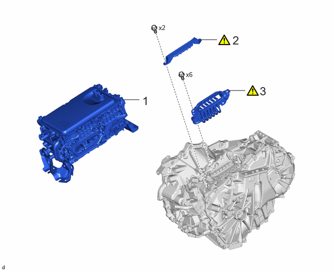
| Procedure | Part Name Code | 
|

|

|
|
|---|---|---|---|---|---|
| 1 | INVERTER WITH CONVERTER ASSEMBLY | G92A0 | - | - | - |
| 2 | TERMINAL CAP | 82823M | ( 202307,999999,_52,_144756,_0603117,RM100000002BO7R_01_0060,) 202307,999999,_52,_144756,_0603117,RM100000002BO7R_01_0060,)
|
- | - |
| 3 | MOTOR CABLE | G1148 | (202307,999999,_52,_144756,_0603117,RM100000002BO7R_01_0059,)
|
- | - |
CAUTION / NOTICE / HINT
- HINT:
-
When the cable is disconnected / reconnected to the auxiliary battery terminal, systems temporarily stop operating. However, each system has a function that completes learning the first time the system is used.
- ·
Learning completes when vehicle is driven
Effect/Inoperative Function When Necessary Procedures are not Performed Necessary Procedures Link Front camera system Drive the vehicle straight ahead at 15 km/h (10 mph) or more for 1 second or more. ( 202307,999999,_95,_112293,_0586709,RM100000002BSVY,)
·Learning completes when vehicle is operated normally
Effect/Inoperative Function When Necessary Procedures are not Performed Necessary Procedures Link Power door lock control system
·Back door opener
Perform door unlock operation with door control switch or electrical key transmitter sub-assembly switch. ( 202201,999999,_58,_115226,_0510939,RM1000000020BSY,)
Power back door system Fully close the back door by hand.
- HINT:
-
Initialization is not necessary if the above procedures are performed while the back door is closed.
( 202201,999999,_59,_113746,_0504731,RM100000001ZJKP,)
Air conditioning system After the ignition switch is turned to ON, the servo motor standard position is recognized. -
CAUTION / NOTICE / HINT
- CAUTION:
- ·
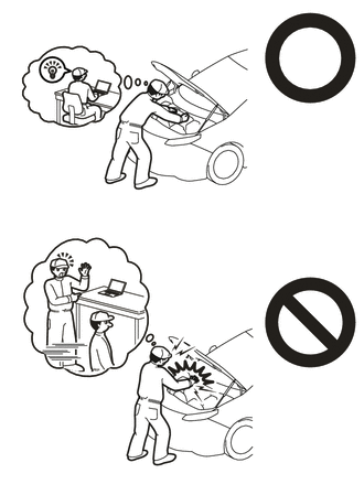
This vehicle has contains high voltage circuits standardized with orange colored wiring and connectors, so follow the instructions in this manual to perform the procedures correctly.
·If the correct procedures are not followed according to the instructions in this manual, there is a danger of electric shock from the high voltage circuits.
·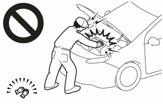
Be sure to wear insulating gloves when working on high voltage wiring or components.
·If work is performed without wearing insulating gloves, there is a danger of electric shock.
PROCEDURE

 G9200
1.REMOVE INVERTER WITH CONVERTER ASSEMBLY
G9200
1.REMOVE INVERTER WITH CONVERTER ASSEMBLY
82823M
2.REMOVE TERMINAL CAP
|
|
|
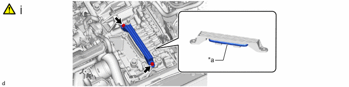
| *a | Waterproof Seal | - | - |
Remove the 2 bolts and terminal cap from the hybrid vehicle transaxle assembly.
- NOTICE:
- ·
Keep the motor cable terminals and their installation area free from foreign matter, water, etc.
·Do not touch the waterproof seal of the terminal cap or terminals of the motor cable.
G1148
3.REMOVE MOTOR CABLE
|
|
|
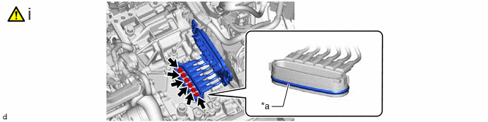
| *a | Waterproof Seal | - | - |
Using an insulated tool, remove the 6 bolts and motor cable from the hybrid vehicle transaxle assembly.
- NOTICE:
- ·
Keep the motor cable terminals and their installation area free from foreign matter, water, etc.
·Do not touch the waterproof seal or terminals of the motor cable.
·After removing the motor cable, cover the opening of the hybrid vehicle transaxle assembly with tape (non-residue type) or equivalent to prevent entry of foreign matter and water.