METER / GAUGE / DISPLAY METER / GAUGE SYSTEM B132887 Lost Communication with Navigation System (Ethernet) Missing Message
DESCRIPTION
This DTC is stored when an Ethernet communication malfunction occurs between the combination meter assembly and radio and display receiver assembly.
| DTC No. | Detection Item | DTC Detection Condition | Trouble Area |
|---|---|---|---|
| B132887 | Lost Communication with Navigation System (Ethernet) Missing Message | Diagnosis Condition:
·
The combination meter assembly has started ·
The radio and display receiver assembly has started ·
IG power source voltage is 9.5 V or more Malfunction Status:
No communication with radio and display receiver assembly Malfunction Time:
34.5 seconds or more |
·
Radio and display receiver assembly ·
Harness or connector ·
Combination meter assembly |
WIRING DIAGRAM
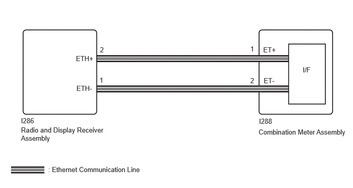
CAUTION / NOTICE / HINT
- NOTICE:
- ·
When replacing the combination meter assembly, always replace it with a new one. If a combination meter assembly which was installed to another vehicle is used, the information stored in it will not match the information from the vehicle and a DTC may be stored.
·When replacing the combination meter assembly, update the ECU security key.
PROCEDURE
Disconnect the I286 radio and display receiver assembly connector.
Disconnect the I288 combination meter assembly connector.
Measure the resistance according to the value(s) in the table below.
- Standard Resistance:
Tester Connection Condition Specified Condition I286-2 (ETH+) - I288-1 (ET+) Always Below 1 Ω I286-1 (ETH-) - I288-2 (ET-) Always Below 1 Ω I286-2 (ETH+) or I288-1 (ET+) - Body ground Always 10 kΩ or higher I286-1 (ETH-) or I288-2 (ET-) - Body ground Always 10 kΩ or higher
- Result:
Proceed to OK NG
OK
NG
Replace the radio and display receiver assembly with a new or known good one.
- HINT:
- Result:
Proceed to NEXT
NEXT
Clear the DTCs.
- Body Electrical > Combination Meter > Clear DTCs
- 50002 409
- Result:
Proceed to NEXT
NEXT
Wait 35 seconds or more.
Check for DTCs.
- Body Electrical > Combination Meter > Trouble Codes
- 50001 409
- Result:
Result Proceed to DTC B132887 is not output A DTC B132887 is output B
A
B