M20F-FXS, M20G-FXS COOLING COOLING FAN SYSTEM Cooling Fan Circuit
DESCRIPTION
The ECM turns on or off the fan relays using signals calculated from the engine coolant temperature, air conditioning switch (on/off), air conditioning refrigerant pressure, engine speed and vehicle speed signals.
The ECM switches the circuit of the cooling fan motors between series and parallel by turning on or off the fan relays in order to control the speed of the cooling fan motors in two steps.
WIRING DIAGRAM
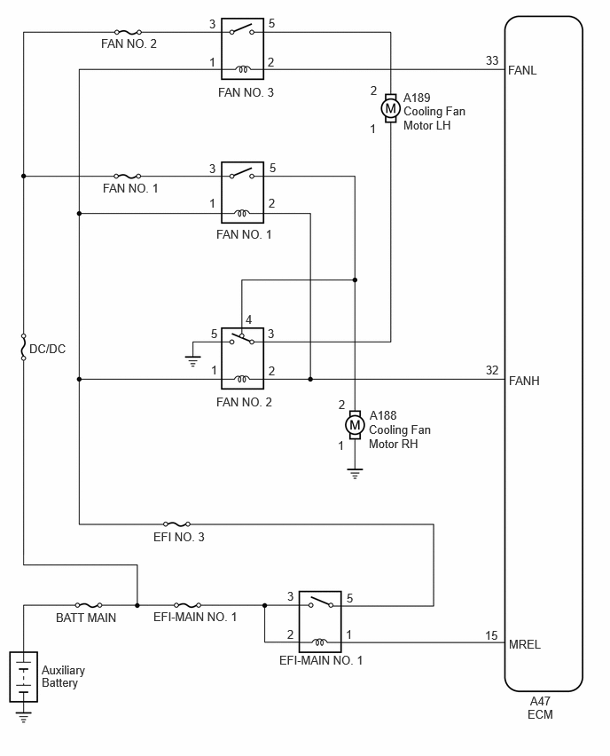
CAUTION / NOTICE / HINT
- NOTICE:
- ·
Inspect the fuses for circuits related to this system before performing the following procedure.
·Before replacing the ECM, refer to Service Bulletin.
PROCEDURE
Connect the GTS to the DLC3.
Turn the ignition switch to ON (IG)
Turn the GTS on.
Enter the following menus: Powertrain / Engine / Active Test / Control the Engine Cooling Fan.
- Powertrain > Engine > Active Test
-
Tester Display Control the Engine Cooling Fan - 50004 372 26
Perform the Active Test according to the display on the GTS.
- OK:
Active Tester Operation Fan Operation HIGH Cooling fans high speed operate LOW Cooling fans low speed operate OFF Cooling fans stop
- Result:
Proceed to OK NG
OK
NG
Disconnect the A46 ECM connector.
Turn the ignition switch to ON (IG)
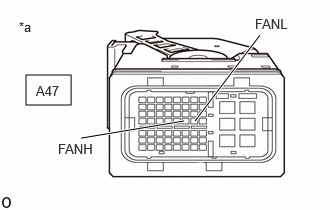
| *a | Front view of wire harness connector
(to ECM) |
Measure the voltage according to the value(s) in the table below.
- Standard Voltage:
Tester Connection Condition Specified Condition A47-32 (FANH) - Body ground Ignition switch ON 11 to 14 V A47-33 (FANL) - Body ground Ignition switch ON 11 to 14 V
- Result:
Proceed to OK NG
OK
NG
Remove the FAN NO. 1 relay from the No. 2 relay block.
Remove the FAN NO. 3 relay from the No. 1 engine room relay block and No. 1 junction block assembly.
Measure the voltage according to the value(s) in the table below.
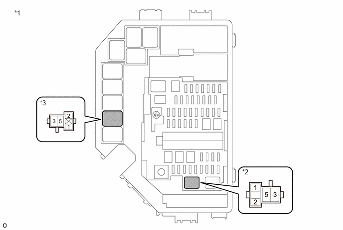
| *1 | No. 1 Engine Room Relay Block and No. 1 Junction Block Assembly | *2 | FAN NO. 1 Relay |
| *3 | FAN NO. 3 Relay | - | - |
- Standard Voltage:
Tester Connection Condition Specified Condition 3 (FAN NO. 1 relay) - Body ground Always 11 to 14 V 3 (FAN NO. 3 relay) - Body ground Always 11 to 14 V
- Result:
Proceed to OK NG
OK
NG
Inspect the FAN NO. 1 relay, FAN NO. 2 relay and FAN NO. 3 relay.
- Result:
Result Proceed to OK A NG (FAN NO. 1 relay) B NG (FAN NO. 2 relay) C NG (FAN NO. 3 relay) D
A
B
C
D
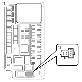
| *1 | No. 1 Engine Room Relay Block and No. 1 Junction Block Assembly |
| *2 | FAN NO. 2 Relay |
Remove the FAN NO. 2 relay from the No. 1 engine room relay block and No. 1 junction block assembly.
Measure the resistance according to the value(s) in the table below.
- Standard Resistance (Check for Open):
Tester Connection Condition Specified Condition 5 (FAN NO. 2 relay) - Body ground Always Below 1 Ω
- Result:
Proceed to OK NG
OK
NG
- CAUTION:
-
To prevent injury due to contact with an operating cooling fan, keep your hands and clothing away from the cooling fans when inspecting the cooling fan system.
Disconnect the cooling fan motor RH connector.
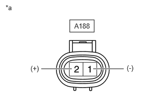
| *a | Component without harness connected
(Cooling Fan Motor RH) |
Check that the cooling fan motor RH operates smoothly when the auxiliary battery is connected to the cooling fan motor RH connector.
Measure the current while the cooling fan motor RH is operating.
- Standard Current:
Condition Specified Condition Auxiliary battery voltage applied at 20°C (68°F) 6.8 to 12.7 A
- Result:
Proceed to OK NG
OK
NG
Disconnect the A188 cooling fan motor RH connector.
Measure the resistance according to the value(s) in the table below.
- Standard Resistance (Check for Open):
Tester Connection Condition Specified Condition A188-1 - Body ground Always Below 1 Ω
- Result:
Proceed to OK NG
OK
NG
Disconnect the A188 cooling fan motor RH connector.
Remove the FAN NO. 1 relay from the No. 2 relay block.
Remove the FAN NO. 2 relay from the No. 1 engine room relay block and No. 1 junction block assembly.
Measure the resistance according to the value(s) in the table below.
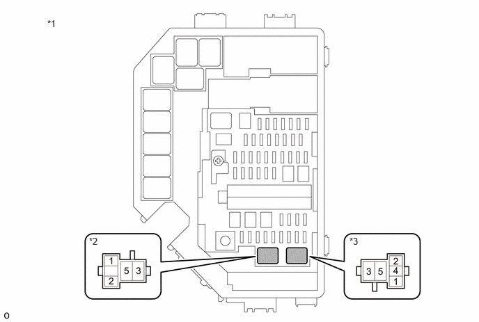
| *1 | No. 1 Engine Room Relay Block and No. 1 Junction Block Assembly | *2 | FAN NO. 1 Relay |
| *3 | FAN NO. 2 Relay | - | - |
- Standard Resistance (Check for Open):
Tester Connection Condition Specified Condition A188-2 - 5 (FAN NO. 1 relay) Always Below 1 Ω A188-2 - 4 (FAN NO. 2 relay) Always Below 1 Ω
- Standard Resistance (Check for Short):
Tester Connection Condition Specified Condition A188-2 or 5 (FAN NO. 1 relay) - Body ground Always 10 kΩ or higher A188-2 or 4 (FAN NO. 2 relay) - Body ground Always 10 kΩ or higher
- Result:
Proceed to OK NG
OK
NG
- CAUTION:
-
To prevent injury due to contact with an operating cooling fan, keep your hands and clothing away from the cooling fans when inspecting the cooling fan system.
Disconnect the cooling fan motor LH connector.
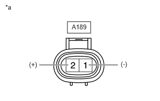
| *a | Component without harness connected
(Cooling Fan Motor LH) |
Check that the cooling fan motor LH operates smoothly when the auxiliary battery is connected to the cooling fan motor LH connector.
Measure the current while the cooling fan motor LH is operating.
- Standard Current:
Condition Specified Condition Auxiliary battery voltage applied at 20°C (68°F) 6.8 to 12.7 A
- Result:
Proceed to OK NG
OK
NG
Disconnect the A189 cooling fan motor LH connector.
Remove the FAN NO. 2 relay and FAN NO. 3 relay from the No. 1 engine room relay block and No. 1 junction block assembly.
Measure the resistance according to the value(s) in the table below.
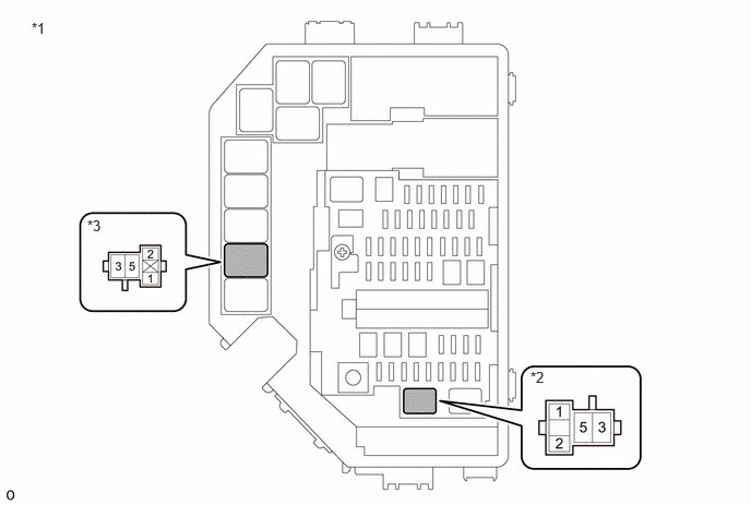
| *1 | No. 1 Engine Room Relay Block and No. 1 Junction Block Assembly | *2 | FAN NO. 1 Relay |
| *3 | FAN NO. 3 Relay | - | - |
- Standard Resistance (Check for Open):
Tester Connection Condition Specified Condition A189-1 - 3 (FAN NO. 2 relay) Always Below 1 Ω A189-2 - 5 (FAN NO. 3 relay) Always Below 1 Ω
- Standard Resistance (Check for Short):
Tester Connection Condition Specified Condition A189-1 or 3 (FAN NO. 2 relay) - Body ground Always 10 kΩ or higher A189-2 or 5 (FAN NO. 3 relay) - Body ground Always 10 kΩ or higher
- Result:
Proceed to OK NG
OK
NG
Remove the FAN NO. 1 relay from the No. 2 relay block.
Remove the FAN NO. 2 relay from the No. 1 engine room relay block and No. 1 junction block assembly.
Measure the resistance according to the value(s) in the table below.
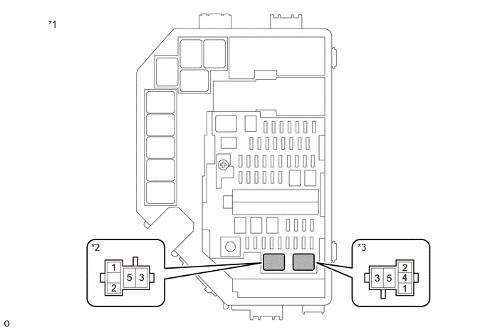
| *1 | No. 1 Engine Room Relay Block and No. 1 Junction Block Assembly | *2 | FAN NO. 1 Relay |
| *3 | FAN NO. 2 Relay | - | - |
- Standard Resistance (Check for Open):
Tester Connection Condition Specified Condition 1 (FAN NO. 1 relay) - 1 (FAN NO. 2 relay) Always Below 1 Ω 2 (FAN NO. 1 relay) - 1 (FAN NO. 2 relay) Always Below 1 Ω
- Standard Resistance (Check for Short):
Tester Connection Condition Specified Condition 1 (FAN NO. 1 relay) or 1 (FAN NO. 2 relay) - Body ground Always 10 kΩ or higher 2 (FAN NO. 1 relay) or 2 (FAN NO. 2 relay) - Body ground Always 10 kΩ or higher
- Result:
Proceed to OK NG
OK
NG
Inspect the FAN NO. 1 relay, FAN NO. 2 relay and FAN NO. 3 relay.
- Result:
Result Proceed to OK A NG (FAN NO. 1 relay) B NG (FAN NO. 2 relay) C NG (FAN NO. 3 relay) D
A
B
C
D
Remove the FAN NO. 1 relay from the No. 2 relay block.
Remove the FAN NO. 2 relay and FAN NO. 3 relay from the No. 1 engine room relay block and No. 1 junction block assembly.
Measure the voltage according to the value(s) in the table below.
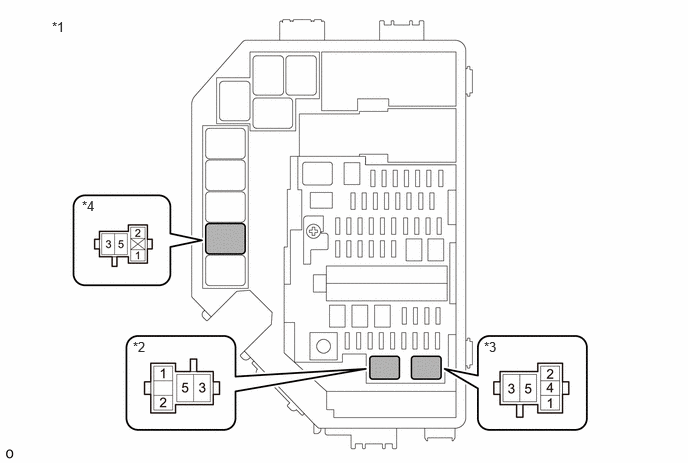
| *1 | No. 1 Engine Room Relay Block and No. 1 Junction Block Assembly | *2 | FAN NO. 1 Relay |
| *3 | FAN NO. 2 Relay | *4 | FAN NO. 3 Relay |
- Standard Voltage:
Tester Connection Condition Specified Condition 1 (FAN NO. 1 relay) - Body ground Always 11 to 14 V 1 (FAN NO. 2 relay) - Body ground Always 11 to 14 V 1 (FAN NO. 3 relay) - Body ground Always 11 to 14 V
- Result:
Proceed to OK NG
OK
NG
Remove the FAN NO. 1 relay from the No. 2 relay block.
Remove the FAN NO. 2 relay and FAN NO. 3 relay from the No. 1 engine room relay block and No. 1 junction block assembly.
Remove the No. 1 integration relay from the No. 1 engine room relay block and No. 1 junction block assembly.
Disconnect the 2B No. 1 integration relay connector.
Measure the resistance according to the value(s) in the table below.
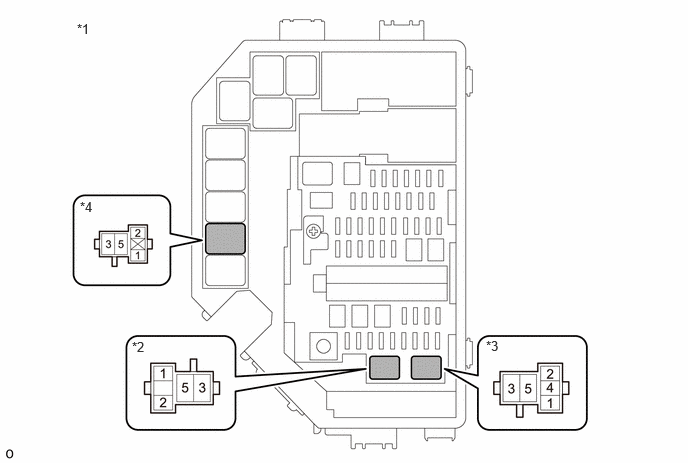
| *1 | No. 1 Engine Room Relay Block and No. 1 Junction Block Assembly | *2 | FAN NO. 1 Relay |
| *3 | FAN NO. 2 Relay | *4 | FAN NO. 3 Relay |
- Standard Resistance (Check for Open):
Tester Connection Condition Specified Condition 1 (FAN NO. 1 relay) - 5 (EFI-MAIN NO. 1 relay) Always Below 1 Ω 1 (FAN NO. 2 relay) - 5 (EFI-MAIN NO. 1 relay) Always Below 1 Ω 1 (FAN NO. 3 relay) - 5 (EFI-MAIN NO. 1 relay) Always Below 1 Ω
- Standard Resistance (Check for Short):
Tester Connection Condition Specified Condition 1 (FAN NO. 1 relay) or 5 (EFI-MAIN NO. 1 relay) - Body ground Always 10 kΩ or higher 1 (FAN NO. 2 relay) or 5 (EFI-MAIN NO. 1 relay) - Body ground Always 10 kΩ or higher 1 (FAN NO. 3 relay) or 5 (EFI-MAIN NO. 1 relay) - Body ground Always 10 kΩ or higher
- Result:
Proceed to OK NG
OK
NG
Remove the EFI-MAIN NO. 1 relay from the No. 1 engine room relay block and No. 1 junction block assembly.
Disconnect the EFI-MAIN NO. 1 relay connector.
Measure the voltage according to the value(s) in the table below.
- Standard Voltage:
Tester Connection Condition Specified Condition 3 (EFI-MAIN NO. 1 relay) - Body ground Always 11 to 14 V
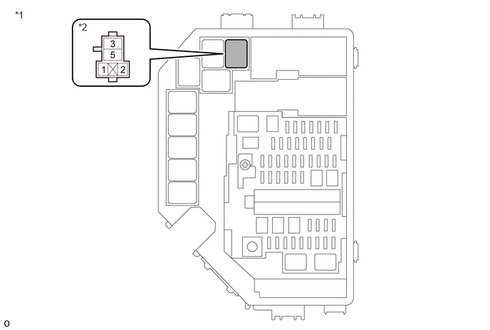
| *1 | No. 1 Engine Room Relay Block and No. 1 Junction Block Assembly | *2 | EFI-MAIN NO. 1 Relay |
- Result:
Proceed to OK NG
OK
NG
Remove the EFI-MAIN NO. 1 relay from the No. 1 engine room relay block and No. 1 junction block assembly.
Disconnect the EFI-MAIN NO. 1 relay connector.
Measure the resistance according to the value(s) in the table below.
- Standard Resistance:
Tester Connection Condition Specified Condition EFI-MAIN NO. 1-2 (EFI-MAIN NO. 1 relay) Always Below 1 Ω
- Result:
Proceed to OK NG
OK
NG
Disconnect the A47 ECM connector.
Disconnect the EFI-MAIN NO. 1 relay connector.
Measure the resistance according to the value(s) in the table below.
- Standard Resistance (Check for Open):
Tester Connection Condition Specified Condition A47-15 (MREL) - 1(EFI-MAIN NO. 1 relay) Always Below 1 Ω
- Standard Resistance (Check for Short):
Tester Connection Condition Specified Condition A47-15 (MREL) or 1(EFI-MAIN NO. 1 relay) - Body ground Always 10 kΩ or higher
- Result:
Proceed to OK NG
OK
NG