RM38T0EC
_51
Engine / Hybrid System
_144716
M20F-FXS, M20G-FXS COOLING
_0603001
RELAY
G
M20F-FXS, M20G-FXS COOLING RELAY ON-VEHICLE INSPECTION
PROCEDURE

 85927
1.INSPECT FAN NO. 1 RELAY
85927
1.INSPECT FAN NO. 1 RELAY
a.
1.823,0.188 1.938,0.188
1.938,0.188 2.031,0.563
false
2.823,0.188 2.708,0.188
2.708,0.188 2.625,0.563
false
2.542,1.104 2.938,1.104
false
2.542,1.594 2.948,1.594
false
2.979,1.51 3.125,1.688
0.146,0.177
10
false
3
0.198,0.74 0.344,0.917
0.146,0.177
10
false
3
2.875,0.104 3.021,0.281
0.146,0.177
10
false
2
1.229,1.281 1.375,1.458
0.146,0.177
10
false
2
0.198,1.271 0.344,1.448
0.146,0.177
10
false
1
1.729,0.094 1.875,0.271
0.146,0.177
10
false
1
2.969,1.01 3.115,1.188
0.146,0.177
10
false
5
1.229,0.75 1.375,0.927
0.146,0.177
10
false
5
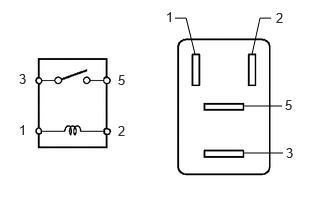
Measure the resistance according to the value(s) in the table below.
- Standard Resistance:
Tester Connection Condition Specified Condition 3 - 5 Auxiliary battery voltage not applied between terminals 1 and 2 10 kΩ or higher 3 - 5 Auxiliary battery voltage applied between terminals 1 and 2 Below 1 Ω
If the result is not as specified, replace the FAN NO. 1 relay.
85927A
2.INSPECT FAN NO. 2 RELAY
a.
2.479,1.135 3.021,1.135
true
2.479,1.635 3.021,1.635
true
1.625,0.74 2.021,0.74
true
2.625,0.74 3.104,0.74
true
2.333,0.625 2.479,0.125
2.479,0.125 2.646,0.125
true
1.292,0.885 1.448,1.083
0.156,0.198
10
false
5
0.948,0.438 1.104,0.635
0.156,0.198
10
false
4
0.354,0.875 0.51,1.073
0.156,0.198
10
false
3
0.354,1.427 0.51,1.625
0.156,0.198
10
false
1
1.292,1.427 1.448,1.625
0.156,0.198
10
false
2
1.531,0.646 1.688,0.844
0.156,0.198
10
false
1
2.698,0.042 2.854,0.24
0.156,0.198
10
false
4
3.063,1.052 3.219,1.25
0.156,0.198
10
false
5
3.052,1.552 3.208,1.75
0.156,0.198
10
false
3
3.146,0.656 3.302,0.854
0.156,0.198
10
false
2
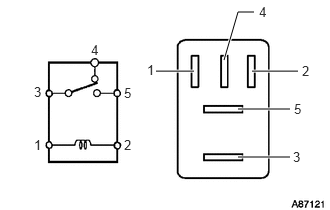
Measure the resistance according to the value(s) in the table below.
- Standard Resistance:
Tester Connection Condition Specified Condition 3 - 4 Auxiliary battery voltage not applied between terminals 1 and 2 Below 1 Ω 3 - 4 Auxiliary battery voltage applied between terminals 1 and 2 10 kΩ or higher 3 - 5 Auxiliary battery voltage not applied between terminals 1 and 2 10 kΩ or higher 3 - 5 Auxiliary battery voltage applied between terminals 1 and 2 Below 1 Ω
If the result is not as specified, replace the FAN NO. 2 relay.
85927B
3.INSPECT FAN NO. 3 RELAY
a.
1.823,0.188 1.938,0.188
1.938,0.188 2.031,0.563
false
2.823,0.188 2.708,0.188
2.708,0.188 2.625,0.563
false
2.542,1.104 2.938,1.104
false
2.542,1.594 2.948,1.594
false
2.979,1.51 3.125,1.688
0.146,0.177
10
false
3
0.198,0.74 0.344,0.917
0.146,0.177
10
false
3
2.875,0.104 3.021,0.281
0.146,0.177
10
false
2
1.229,1.281 1.375,1.458
0.146,0.177
10
false
2
0.198,1.271 0.344,1.448
0.146,0.177
10
false
1
1.729,0.094 1.875,0.271
0.146,0.177
10
false
1
2.969,1.01 3.115,1.188
0.146,0.177
10
false
5
1.229,0.75 1.375,0.927
0.146,0.177
10
false
5
Measure the resistance according to the value(s) in the table below.
- Standard Resistance:
Tester Connection Condition Specified Condition 3 - 5 Auxiliary battery voltage not applied between terminals 1 and 2 10 kΩ or higher 3 - 5 Auxiliary battery voltage applied between terminals 1 and 2 Below 1 Ω
If the result is not as specified, replace the FAN NO. 3 relay.